I’ve always felt the weak link in the fueling system of our platform is the in-tank (or low pressure fuel pump – LPFP). This isn’t normally an issue with mild to semi-aggressive builds as the addition of a higher output HPFP and injectors along with an ethanol blend and maybe even some methanol injection have been able to keep up with the majority of the demands of the platform.
However, the reality of it is that no one has really taken this platform to extremes quite yet (mostly because the transmission can’t take it). Those extremes include running straight e85 and/or wheel horsepower levels exceeding the 650-700 mark. It’s those areas were serious fuel demands come into play and simply installing larger injectors and HPFP just won’t do the trick. In order to address this high fuel demand issue, we need to look at the very first step of the fuel system, the in-tank pump. My breakdown of it is that, with those other components, you’ve basically got yourself a fire hose nozzle attached to standard garden hose bib. At the extreme end of the spectrum, you’ll just never be able to feed that nozzle with what it needs to truly shine.
I’ve recently began running straight e85, and already the cracks are starting to show in the armor. According to my tuner, we’d like to see a low pressure side reading of at least 80psi. Well, at WOT, we were seeing dips down into the 60psi range, and the HPFP would follow with a dip in output and/or increase in duty cycle.
Now, I have been preaching that the low-pressure pump is the weak link and to that end, I have explored many, many different options (surge tanks, larger in-tank pumps, etc.). None quite off the table, but most of them are very complex problems to solve and, frankly, exceed my limits of advanced fuel system knowledge. So, to that end, after speaking with Uwe over at XDI who was attempting to install a larger Bosch 400 into a stock fuel bucket I had sent him and found that it just wasn’t quite possible reminded me of an old trick that may be able to be revived and used in our platform.
Enter the fuel pump voltage booster…
Known to many as a Boost-A-Pump, or BAP (although that title is usually in reference to the Kenne Bell version of the device). The theory here is, the more voltage to the pump, the more work it can do. Pretty simple, right? Well, it’s a bit more involved than that…so here goes.
The OEM fuel system in our platform is a return-less, pulse-width modulated (PWM), direct injection system. What that basically means is, there is a fuel pump driver module (FPDM) that is sending PWM signals to maintain a system pressure on the low pressure side that the HPFP can use to push the rail pressures to above the 2000psi mark. It isn’t like the old school pumps that just ramp up and down in speed to maintain that pressure, but rather, turn off and on at an incredibly fast rate. This means, you can’t simply interrupt the voltage signal going directly to the pump, you need to interrupt the signal pre-FPDM.
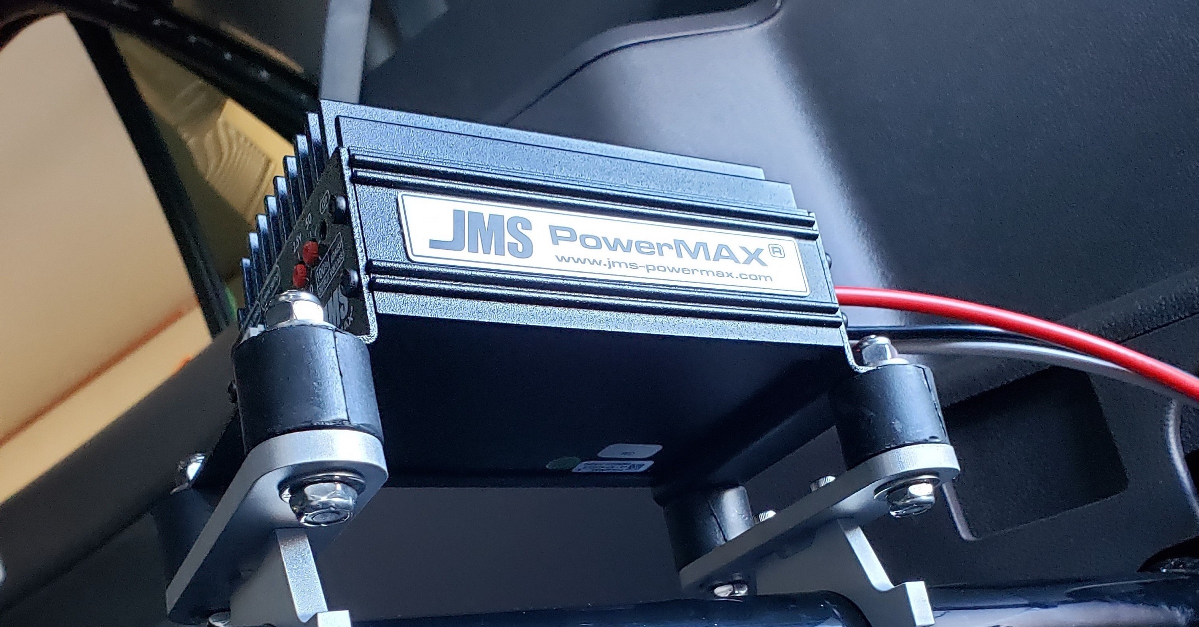
So, on the advice of Carl over at Vapor Worx, I decided to go with the JMS version instead of the Kenne Bell or MSD. The JMS version has a reputation for having the cleanest output signal and has some pretty cool ramp in/out features that I found I’d like to use as well as being able utilize a 0-5vdc trigger if required.
It comes with everything you need to get this thing up and running. That includes a Hobbs switch for using boost as a reference if you are so inclined…
Triggering the pump…
However, I really wanted to utilize the 0-5vdc trigger feature of this device as it allows you to fine tune a ramp in/out rate if you desire (and I do). So where do I get a 0-5vdc reference? Hmmmmm…well, you really DON’T want to tap into the MAP sensor signal as the act of tapping it can sometimes introduce noise into the system and have weird effects on the vehicle. You also don’t want to tap into the Throttle Position Sensor (TPS) as that can open and close at various positions not equating to actual fuel demand. I guess I could install a second, dedicated MAP sensor, but that would be over-engineering the solution. Why not just go with a solution that JMS already had in-place. Use of the accelerator pedal position (APP) sensor. Because I like plug-n-play, along with the ability to “EDIT/UNDO”, I opted for an off-the-shelf solution from JMS.
Since I was going to use the pedal position as my 0-5vdc reference, I had to see what the actual range of output was. Just because it is a 0-5vdc output doesn’t mean it’s at that exact range.
This test was done key-on, engine-off.
Next was accessing the FPDM. Even though it is underneath the c-pillar cover, because of the way Ford decided to assemble this car, you have to remove almost the entire rear interior, lol….ugh…..
Here is everything off but placed loosely back into position, other than the c-pillar cover:
It was at this point that I did some data collection on what the FPDM is seeing. I have two Fluke meters so I decided to also see how that voltage compares to what the pedal sensor is putting out. Here’s a video compilation:
I have plans to wire this in such a way that I can remove the BAP and put it back to stock relatively easily. This requires the use of my extensive Deutsch connector set:
Just one wire from the FPDM to this connector:
As you can see it has 2 wires, one going to an existing ground. When it’s connected in OEM configuration, it goes nowhere, but when it is connected in BAP configuration, it will be the ground for the BAP wire.
And here it is in full OEM configuration.
Now onto the BAP connector itself. The wires are just cut wild when you get it from JMS, but I took a page out of the MSD book and used a DTP Deutsch connector end here as well:
Now to make the harness that connects the BAP to the FPDM using more DTP Deutsch connectors:
I’m going to leave one end wild for the time being until I identify where the BAP will be physically mounted so I can figure how long the other end needs to be.
Mounting location and brackets
I decided I would secure the device to the roll bar that is in the cargo area. Thought it would look pretty trick and also be close to the FPDM.
For the base brackets, I used some 1″ by 0.25″ aluminum bar stock I had laying around. I cut two pieces 4.125″ long and started measuring them up for some mounting holes:
I’ll round the edges and make it look nice and likely powdercoat these as well.
For the roll bar attachment, I got 2 of the 1.50″ Longacre mounts:
There was one small issue. The roll bar wasn’t an exact 1.50″, it was more like 1.55″. Not much, but enough for it to not fit properly. I was going to have to do a little bit of grinding on it…so I conveniently had a spacer laying around that was 1.50″ with a shoulder of 1.60″. It worked out pretty nicely to give me an edge to go off of:
I’ll likely powdercoat these along with the above brackets. In addition to the brackets, I used some of these rubber isolators to give it some vibration dampening:
Now I can start making the connecting wire harness. It’s running behind the wheel well panel cover and up to the c-pillar:
After marking where I need to trim and where the terminal ends need to go, here’s the final piece to the puzzle:
So, JMS calls for replacement of the FPDM fuse and upgrade it to a 30A fuse. Well, it just so happens, the fuse for our platform’s FPDM is already 30A (the only green fuse in the photo). It’s found in the Battery Junction Box under the hood, position F65:
Once that is done, now it’s time to crank it up, do some testing setup and test this puppy out! This is a hot mess as I’m simply doing setup/testing to make sure everything works:
So, what settings am I using, you ask? Well, According to Deatschwerks, the pump is good for spurts of 18.0vdc. The highest I saw this at WOT was about 14.8vdc. I want to ease into it for now, so I’m not going to go over 17.0vdc.
Device settings
So, I got it setup for maximum voltage boost of 17.0vdc. Using the pedal position sensor, I want to ramp it in using the largest ramp the unit allows for, a 1.2vdc sensor ramp. I have it set to begin boosting at a sensor reading of ~1.40vdc (~20% “throttle”), which means it is at full 17.0vdc at ~2.60vdc (~55% “throttle”).
During testing at idle, it sees standard vehicle voltage, but as soon as the pedal is depressed, once it gets to the 1.4vdc value, you can see the FPDM voltage increasing. Now to take it on the road and see how it responds…
…road testing turned out interesting and I’m actually very pleased at the improved pressure readings. I did a log both before and after. Here are the results, all else was equal including the tune. This was a 3rd gear run from 2k RPM all the way to 6k RPM.
Before BAP
Green = Low Pressure Actual
Before BAP
Blue = High Pressure Actual
Before BAP
Blue = High Pressure Actual
With BAP (no tune revision)
Green = Low Pressure Actual
With BAP (no tune revision)
Blue = High Pressure Actual
With BAP (no tune revision)
Blue = High Pressure Actual
As you can see, the low-side actual pressure was quite a bit better than the run without the BAP. This tells me there is a bit more flow. It could still use some help at the end, but it’s markedly better.
So, now that testing is done, onto final assembly…
And all the small pieces soda-blasted. I’m leaving it raw aluminum but may end up powder coating them once I get enough other stuff to make a decent size run:
And I decided to leave that small c-pillar panel off permanently for weight savings! No, seriously, I’m going to leave it off as I may need to access this area from time to time. One issue is the seat belt goes through it. I’ve got the airbag seat belts so it took a few steps trying to figure out how to get that big click connector through the hole without cutting the panel.
Separate the plastic halves. They just pry apart:
You’ll have to push down on the spring metal tab under this side of the pin and pull the pin out. The tab holds the pin in place:
Here is the pin removed, and you can see how it holds everything together:
And here you see everything separated. Just pull the belt through the hole of the c-pillar cover and re-assemble the seat belt…too easy:
The trigger wire that goes to the pedal position sensor I am running down the other side of the vehicle. Here’s the other interior panel off:
Running it down the rear passenger door sill:
Front driver door sill:
And up into the foot pedal area:
Cool little cheap tool I learned to use when I worked at a car stereo install shop…a very large HVAC zip-tie (36″ long or so) with the head cut off. This is an AWESOME tool for feeding wires through places…get em from your big box hardware store. It’s definitely one of my “must-have” tools as it’s been indispensable throughout the years.
Anyway, once the wires were run up into that area, everything was reconnected and tested. All the interior panels where put back together and all is done! Now to go get some datalogs!
So, some results after a tune revision (btw, I’m still dialing this tune in with Brad, so this isn’t the final tune).
With BAP (with tune revision)
Green = Low Pressure Actual
With BAP (with tune revision)
Blue = High Pressure Actual
With BAP (with tune revision)
Blue = High Pressure Actual