- Introduction
- Why all the fuss?
- Where it all begins…
- Parts list
- Repair parts
- Punch list
- Converting to a PTU w/cooler…
- Disassembly
- Assistance…
- UPDATE: June 19th, 2020
- UPDATE: June 21st, 2020
- UPDATE: March 31st, 2022
- New oil fill fitting
- New oil drain fitting
- Avengers assemble!!!
- Completed and testing
Introduction
This is my attempt at doing what little we can to improve the PTU with what is currently available. I’d also like to make it a resource for those of you looking for detailed photos of the latest version of the PTU that has the cooler. I’ve completely torn down the PTU, and sourced all brand-new seals for it.
But before I dive into it completely, here is a brief history of some of the various PTU iterations throughout the years. This is covered and written about more thoroughly in THIS POST.
This information comes from the August 2016 issue of Police Fleet Manager Magazine:
“Power Takeoff Units”
The power takeoff unit (PTU) has been a service concern on some PI Utilities. There may be an excessive oil smell when driving, the AWD may not work properly, or the PTU housing may be cracked, leaking or noisy. The cause of the PTU damage is the excessive torque loading of the idler gear, which causes the bearing to walk (move) into the housing.
In January 2014, a Full Face Thrust Washer, FFTW, was introduced. This new washer was designed to prevent the idler bearing from walking into the aluminum case. In October 2015, a second change was made, in this case a loose-fit idler bearing. In dynamometer tests, this bearing design change showed a twice life improvement over the FFTW design.
In June 2016, a third change was made. In this case, a new bearing design, one without drawn cups, was installed. This eliminated the walk mode of damage. Dyno testing shows a three to four times improvement over the FFTW design. For both the PI Utility and PI Sedan, the PTU is covered under the limited powertrain warranty. All Ford Police Interceptors come standard with a five-year/100,000-mile Extended Service Plan for the powertrain.”
Why all the fuss?
The Ford PTU, which is found in millions of vehicles on the road today, is notorious for failing. Despite many of the improvements you read about in the previous section that Ford made, there are still some fundamental issues with it. And even so, if you’ve got an older PTU, you’re still going to be prone to many of the issues the newer iterations attempted to address.
Where it all begins…
In this photo it looks like the vehicle is beginning to experience some of those dreaded PTU failure symptoms. Last time I was underneath the vehicle, I saw quite a bit of oil covering the body of the PTU, and soaking the portion of the exhaust that sits underneath it. It hasn’t failed, in that I don’t have any drive-ability issues yet, but it is coming I’m sure. I will say, that I have NOT been proactive with changing of the fluid. Not because I’m lazy but because I was not aware of the PTU issues until very recently. Call it my ignorance on it, but regardless, I’m glad I caught it when I did. It’s a 2015 with just a hair over 30K miles on it. I don’t drive it much, believe it or not, this is pretty much my dedicated project car.
Parts list
- 2013-2019 Ford Transfer Case, DG1Z-7251-F (Qty: 1)
- 2007-2019 Ford Transfer Case Input Shaft Seal, 7T4Z-7086-A (Qty: 1)
- 2007-2020 Ford Input Shaft Seal, 7E5Z-7H469-C (Qty: 2)
- 2007-2019 Ford Transfer Case Output Shaft Seal Kit, DB5Z-7275-E (Qty: 1)
- 2007-2020 Ford Transfer Case Pinion Output Shaft Seal Kit, GB5Z-7275-A (Qty: 1)
- 2007-2020 Ford Output Shaft Seal, 7T4Z-7R284-A (Qty: 1)
- 2012-2019 Ford Gasket, DG1Z-7A191-B (Qty: 1) – NOTICE: Only needed if you have the PTU side cooler.
Repair parts
If you have an older PTU that you want to refurbish or one that might have seen some damage, there is a repair kit. But it is only for damage to the idler gear assembly, which is the most common failure mechanism.
- 2007-2019 Ford PTU Idler Gear Repair Kit, GB5Z-7P258-A (Qty: 1)
- This kit includes these parts from the above Parts List:
- 7T4Z-7086-A (Qty: 1)
- 7E5Z-7H469-C (Qty: 2)
- DB5Z-7275-E (Qty: 1)
- GB5Z-7275-A (Qty: 1)
- 7T4Z-7R284-A (Qty: 1)
- This kit also includes:
- Idler Gear (Qty: 1)
- Idler Gear Bearing (Qty: 2)
- Idler Gear Shaft (Qty: 1)
- Idler Gear Oil Slinger (Qty: 1)
- Idler Gear Oil Slinger Retainer (Qty: 1)
- PTU Oil Drain Plug (Qty: 1)
- PTU Temperature Sensor O-Ring (Qty: 1)
- This kit includes these parts from the above Parts List:
Punch list
Anyway, being the consummate prepper that I am, and wanting to keep downtime to a minimum, I went and purchased a brand new one before I am even taking the old one out.
My punch list for things I want to accomplish with this new PTU are as follows:
- Change drain plug to bottom of case in order to ensure complete drainage of fluid when performing oil changes.
- Extend hose from vent to top of engine bay to facilitate future oil changes and fills.
- Send all gears and cast components to receive WPC treatment (WPC Treatment).
- Send all gears, cast components, bearings and case to receive cryogenic treatment (Nitrofreeze).
- If possible, research possible higher quality bearings to replace existing ones.
- Apply gold metallic radiant heat reflection material to outside of case.
Here it is, brand new and unmolested. Too bad I will be ripping her apart!
Converting to a PTU w/cooler…
Now I want to say, I truly believe if you have an older SHO/Flex/XSport that doesn’t have this cooler, you COULD make this version with the cooler work. It would take some effort, but I am certain it could be accomplished. You’d have to buy the hose:
- 2013-2019 Ford Water Pipe, BB5Z-8A519-G (Qty: 1)
Then run your lines through an aftermarket pump and heat exchanger of some sort. It would be a pretty trick setup if done right.
And for those of you wanting to do just that and get REALLY fancy by using the included temperature probe to wire up to the pump or some sort of temp gauge, I think I did some of the legwork for you on giving you some data on the output of that probe and how it correlates to temperature. I figured since I have it off and I have the tools to do this, I’d pass this onto you guys. What I did was use two of my Fluke meters, using one that has temp reading capability with a probe end right next to the actual probe itself, and use the other meter to read the resistance output of the probe at various temperatures. I created those various temps using ice water then boiled water. I placed the end of the probe into the liquids and took temperature recordings at various intervals. Here is a simple spreadsheet showing the results. This may help those interested in the scaling of this particular temp sending unit:
Disassembly
As I disassembled it, here is what the cooler actually looks like. It isn’t very complex, I wonder if there is any way to improve it. I had entertained the idea of 3D modeling the outside cover for the cooler and then having some sort of heat sinks integrated into it to help further cool down the fluid passing through it. The cooler medium is called a “gasket” by Ford and if yours is in good shape (especially if its a new PTU), there really is no need to get a new one, but if you do, the part number is:
- 2012-2019 Ford Gasket, DG1Z-7A191-B (Qty: 1)
So, before I started complete disassembly, I ordered a replacement for every single seal, gasket or one-time-use part as I wasn’t sure how much I would destroy trying to take them apart. Below is a list of all the Ford part numbers you will need:
- 2013-2019 Ford Transfer Case, DG1Z-7251-F (Qty: 1)
- 2007-2019 Ford Transfer Case Input Shaft Seal, 7T4Z-7086-A (Qty: 1)
- 2007-2020 Ford Input Shaft Seal, 7E5Z-7H469-C (Qty: 2)
- 2007-2019 Ford Transfer Case Output Shaft Seal Kit, DB5Z-7275-E (Qty: 1)
- 2007-2020 Ford Transfer Case Pinion Output Shaft Seal Kit, GB5Z-7275-A (Qty: 1)
- 2007-2020 Ford Output Shaft Seal, 7T4Z-7R284-A (Qty: 1)
- 2012-2019 Ford Gasket, DG1Z-7A191-B (Qty: 1)
When you take it apart, make sure you have some sort of catch for the oil that will come out, as it comes filled from Ford. I have a large oil drip cookie sheet that I was working on. Worked great! BTW, I forgot how much I hate the smell of gear oil…
When you finally get it apart, you will find it somewhat difficult to remove the gears from the side of the case. In order to remove them, you will have to basically destroy the white end seal/plastic cover (Ford calls it the deflector) that is pressed onto the output shaft seal. Make sure you get a new one, as you WILL destroy this taking the PTU apart. Once it’s off, the gears will all come out one after the other.
I just used an air impact to remove the nut off the end of the pinion gear. That nut will be replaced and is included in the new parts kits. Be advised: many of the seals will have to be destroyed when removing them.
I decided to remove all the seals as I wasn’t sure if my disassembly would damage them at all and, more importantly, they may not survive the cryo process. So, when I send all the parts to cryo, they will be disassembled bare metal.
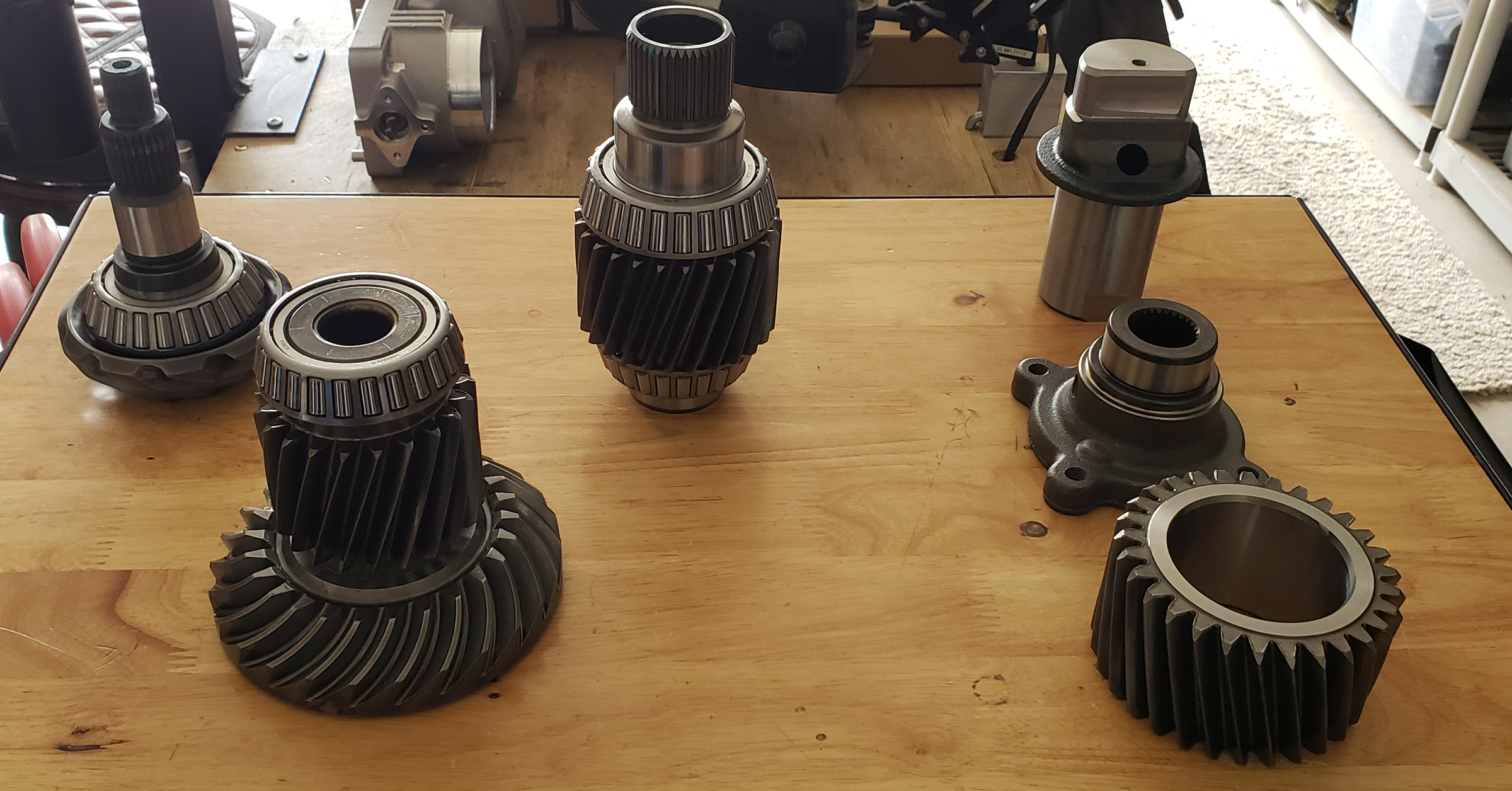
As for the bearings. My goal is to try and source some higher quality ones, if they exist. I imagine Ford made some specifications for bearings they needed, then sent out the contract for the lowest bidder to meet those specs. Most of the bearings are Iljin, whom I’ve never heard of, but looks to be a Korean company. I’ve found some in-depth documentation on some of their bearings but so far, nothing about the ones within the PTU specifically. I’m hoping to find some equivalent or better versions via Timkin or Torrington, maybe some SKFs. I removed as many of the bearings as I could:
The only one I cannot remove was the one behind the pinion gear head. It sits in a recessed pocket and no puller can get behind it without destroying the bearing cage. Even though I will begin the process of looking for better grade bearings, I didn’t want to risk destroying this one as it may end up being a unicorn bearing and not easily sourced/replaced.
Assistance…
Although I have some good resources for locating bearings, I am always open to “crowd-sourcing” this task. If any of you guys have a good bearing “guy”, here are some of the bearing numbers:
Anyway, here are all the parts I’ll be sending to WPC:
I spoke with one of their reps regarding having parts with bearings still pressed onto shafts. Their response was: although they recommend removal of all roller/ball bearings, they CAN still apply the WPC treatment, but it is absolutely imperative that a very extensive and thorough cleaning job be accomplished on the bearing prior to installation. They do ultrasonic cleaning, so it should be pretty good, but I also have a high-quality industrial grade parts washer I will put all the parts through as well once they come back.
The cryo treatment will be performed after the WPC treatment and I will include every metal component I can for that one. It will be sent over disassembled and I will press all the bearings back onto their respective location. I use a bearing heater prior to pressing them on (it gets pretty damn hot) and don’t want that to cancel out any gain provided by the cryo treatment in doing so. I will do final assembly and seal installation after it all comes back home. There is no case gasket but looks like they used something similar to Yamabond, which I’ve used successfully to seal Harley Davidson Twin Cam cases. It should work fine in this instance as well. Then fill it with some Amsoil Severe Gear Oil:
And finally, the piece-de-resistance, the reflective material.
My heart tells me this is snake oil, but my brain tells me that the logic behind it is sound. I figured, what the hell, what harm can it do. It really only works to reflect radiant heat, so not sure how effective it is in the real world, especially where I will be putting it. Anyway, just doing every small thing possible to keep this thing cool, which is really the true killer of this thing.
I know it’s been said that regular oil changes can keep this thing alive, but figured I’d try a few additional steps.
So, right now, I’m getting ready to pack the parts up for the WPC treatment. As I proceed with the PTU build, I’ll post updates…
Thanks!
UPDATE: June 19th, 2020
Internals back from WPC. Now to press the bearings back on and off to cryo…
UPDATE: June 21st, 2020
I know the idea of using a small reservoir was being thrown around and that gave me an idea. I had this thing laying around and it was originally going to be used for my meth tank to be filled remotely. I got it from ProMeth. I’ve since gone to a different meth tank and never used this but it looks perfect for what will be done:
I am also about to extend that vent hose, but…PLOT TWIST…will NOT be connecting it to the reservoir. I’m just going to extend it up higher, just to be higher, LOL. But what I WILL be doing is….drilling for another hose fitting. After reading about how long it can take to get the fluid down the vent hose. I figured the air is just fighting you, but if there was another line…it would be WAY easier. Not only that, but the hose fitting at the bottom of that reservoir allows for a slightly larger hose to be used.
This photo shows me mocking up where it will go, but that isn’t the actual fitting I will use, the actual one will be smaller and stainless…
See…plenty of room inside the PTU for it:
Anyway, should facilitate fluid changes more easy. I’ll update when I get closer.
UPDATE: March 31st, 2022
It’s been a long time since I’ve done anything on this PTU and it’s time some forward progress was made. So I decided to tackle it…starting with the larger fill fitting.
New oil fill fitting
The fitting I went with was a 316 stainless steel, hose barb fitting for 1/2″ tubing and a 1/4 NPT thread. The only thing I didn’t like was that it didn’t have a large enough bore. It is a fitting designed for chemicals, so it is very thick-walled. I ended up running a 3/8″ drill bit down the center to enlarge the hole from 1/4″. Since it’s 316 stainless, it’s tough to drill and needed to be done in steps, with lots of cutting oil.
- Barbed Hose Fitting for Chemicals & Petroleum, 316 Stainless Steel Adapter for 1/2″ Hose ID, 1/4 NPT Male, Qty: 1
Wanted to measure the depth of that internal vent “galley”, to ensure placement of the new oil fill fitting would be in the right place.
New oil drain fitting
Avengers assemble!!!
Assembly is going to start out with a thorough cleaning of all parts. Having access to a parts washer is ideal. If you want to clean everything with Brake-Clean, you’ll need a lot of it…probably a case. Or just use some heavy duty de-greaser and go to town. Just make sure you rinse it out well.
- How to Replace PTU – 2010 EB – www.fordflex.net
Pinion shaft and seal
Internal gear set and side cover
This part of the process began by pressing the bearings back onto the internal gear set. I really only needed to press three of them on. Two on either end of the input shaft gear and one on the snout of the ring gear. A bearing heater really makes this job 10x easier. The amount of pressure needed is so minimal when using one. Care should be taken when pressing bearings, even when using a heater (but especially when NOT using a heater), to ensure they go on straight and true. Avoid using a hammer to drive them on…a press, with constant pressure is ideal. These bearing can’t be sourced individually (that I’ve discovered), so if you mess one up…you’re buying a whole new PTU.
After installation of the pinion gear and flange, it’s time to start putting the rest of the internal gearset together. I initially began with driving the seals for the input shaft into the housing, but quickly realized, it was a bit more difficult than it appeared and that I may need those special driver tools after all. But what I will do instead, as the tools are WAY too expensive to drive those input shaft seals, is make the tools. It isn’t too hard but they need to be pretty precise on the size.
Input shaft seal
Reminder: lubricate the bearings and gear faces with the 75W-140 as you install these parts. This pre-lubes them up and keeps them fresh.
After installing the input gear, the next one is the idler gear. It needs to be assembled with the the idler shaft, 2 needle bearings, then install the idler gear itself over that assembly. Install the flat washer that has a flat internal side to keep it clocked properly, then finally…the plastic retaining ring needs to go over that. It also has an internal flat side to keep it clocked. It’s used to keep the flat washer in place. It also flexes quite a bit, so don’t be shy about pushing it over the idler shaft. It freaked me out that it was going to crack or something, but it just needed to be pushed evenly on two sides simultaneously. I didn’t get any pictures of this part, but see the video.
After the idler gear is installed, you can throw the ring gear into the case. Carefully lay it in there making sure all the teeth from both the idler gear and pinion gear mesh properly.
I used some of the FoMoCo RTV that was used to seal the engine timing cover.
And using the DeWalt battery operated caulking gun made this part of the job soooo easy. I can’t imagine having to use one of those hand pumps. Do yourself a favor and get you one of these, LOL.
Then began the torqueing process. Be aware of the two step sequence.