This was a project that seemed daunting at first, but thanks to Todd over at TCE Performance Products, it turned out to be tedious, but altogether simple. A great company with great customer service, BTW. I highly recommend them.
Documentation
A few caveats: you WILL lose usage of your emergency brake with this kit. Currently there is no way to mount a Wilwood ebrake caliper to it as the mount is not provisioned for it. I may hit Todd back up to see if he is willing to entertain designing a new mount that may allow for the installation of Wilwood’s ebrake caliper, but since these aren’t “flying-off-the-shelves” I’m not sure there is much energy going to go into that. The kits require 19″ diameter wheels at a minimum and if you’re running the stock 20″ wheels, you’ll need a 10mm spacer. All these things were taken care of with my aftermarket wheels, so no worries in my case. I am very appreciative that there is even a kit upgrade at all.
Keep in mind this kit was designed for the Taurus SHO, but since the Explorer and Taurus share so much of their parts, it was virtually plug and play, keyword being “virtually”. We discovered some subtle differences.
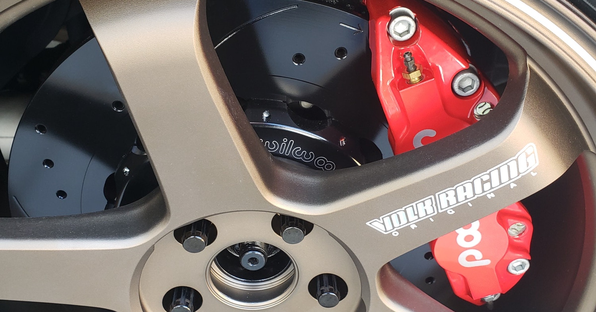
It’s a shame that Ford decided not to go with some Brembo (or even Wilwood) brakes on what would be considered it’s “performance SUV”. It already has the updated heavy-duty setup from the PIU from Ford, and there are a few bolt-on disc upgrades out in the aftermarket. But I wanted to go a step further, probably overkill, but it performs as good as it looks…
I wanted to give my good friend San Man for helping to gather more information on this modification. He was able to fill in some of the information gaps.
Anyway, I will denote what side the photo came from, but bear in mind that what is needed in the front goes for both driver and passenger side, and same for the rear, regardless of what side I took the photo on.
So, starting with the front.
To ensure the brake lines would be similar to OEM in the way they flexed while turning, I took some “before” shots to compare to when install is complete.
Before I installed the new rotors, I knew my aftermarket wheels had no center cap, leaving the hub nut and end of the axle exposed (by choice, the wheels can come with center caps if chosen) so I wanted to clean up the rusted hub nut and axle end. I used a wire brush to get as much rust off as possible and then I sprayed some rust inhibitor onto the exposed portions:
I then installed the rotors onto the front wheel hubs. I used a 1″ spacer and a lug nut to keep the rotor pressed tight against the hub while doing the rest of the installation:
One of the first differences I noticed was, the end of the front brake line that attaches to the vehicle side was nowhere near the type of connection I got from TCE:
After contacting Todd about it, 1 week later I had the proper brass fitting to adapt the new lines to the OEM connection point:
Now, a little about this brass brake “T” fitting, it is NOT included in an SHO kit. The connection point on that platform is one of the differences and should be part of the conversation when ordering your kit from TCE, should you go that route. It can also be gotten from Chris over at Techna-Fit. He is another great person to work with and can handle any of your custom brake line needs. This fitting is based off an F250 brake fitting, and can be seen here, for example, from a 2015 F250 Super Duty front brake line.
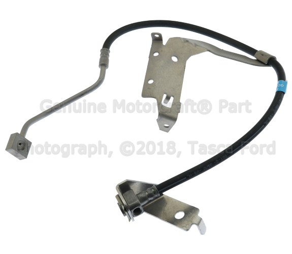
It is held in place on the bracket with that clip. I’ve never seen this brass fitting anywhere other than Techna-Fit so if you are doing something custom, you may need to reach out directly to Chris there.
Here are some images of the brass fitting.
As for the adapter that screws into it, you’ll need part number 10100-03 from Techna-Fit. This, of course, is all in case you are doing something custom as Todd will generally include the parts needed.
To continue, installing the caliper mount is pretty self-explanatory. When mounting the caliper to the mount itself, keep in mind, you don’t want to use Loctite of any kind. You will want to be taking these off when changing pads, so you don’t want these things seized onto the studs. Instead, use some anti-seize so the threads don’t gall while tightening and it helps to lubricate the threads to attain a more accurate torque at the same time:
The first set of brake lines were a little long. I didn’t discover this until it was mounted. The lines were initially about 19″ end-to-end:
As you can see, the lines work, but they are a bit too long for my taste. There was too much potential for the lines to rub on the inside of the wheel or some other part of the wheel well as it travels in various positions while driving. This is where some experimentation came in and I gotta say, Todd came through in a big way on this one. He dealt with my picky-ness and multiple length requests as we nailed down the perfect length. And he sent every single set for free! Now that’s customer service!
About 2 weeks (and about 3 sets) later, we had finally nailed down that 16″ end-to-end was the perfect fit. When ordering a brake line kit, it is imperative that length is “end-to-end”. Some brake line manufacturers sell their brake lines using the measurement of only the actual hose portion and not the crimped end swivel fittings, so double check with a brake line manufacturer if you are doing something custom. It would also be a good idea to mention this to Todd when placing an order:
This arrangement allowed for the necessary amount of flex, but wasn’t too “loose” that it was in danger of rubbing on something.
That completed the installation of the front brakes, now onto the rears. Now, while removal of the stock front dust shield was a simple affair, the rear dust shield was a different story. Because of the way it was installed, the entire wheel hub would have to come off in order to remove it properly. I did not wish to do that, so I took the easy way out…I cut it off. Seeing as I wouldn’t be using it anyway, it wasn’t too big of a deal:
Here is the OEM setup from the inside. Note the angle and positioning of the brake line. I attempted to recreate this angle while the suspension is in its normal, compressed state.
When removing the rear caliper, the emergency brake will have to be disconnected and the line secured somehow. When I disconnected it, I took the loose end and used a metal zip tie (normally used for exhaust wrap) to secure it in a location that will not interfere with suspension travel.
Before you can mount the new rotor, you need to install the caliper mount. Well, before you can do that, for the rear, you’ll need to trim (flatten is a better word) a small amount off of the wheel hub, as denoted with the black sharpie lines.
I just used my trusty angle grinder with a sanding flap-wheel, worked like cutting into butter.
Well, it again came time to ensure the brake lines were of the correct length. The ones Todd sent were 19.5″ long end-to-end which included the custom adapter piece on the end.
There were multiple issues with this line. It was far too long and the fitting that secures with a clip on the vehicle side wasn’t the proper one and the clip was very loose. This length would create issues as it would rub on the inside of the wheel, a potential hazardous scenario. Turns out, a hose that was 17″ long end-to-end to include the now-integrated proper end fitting was what was needed.
Here you can see that angle I attempted to recreate, in order to keep the line from rubbing the inside of the wheel.
And that was it…last thing to do was bleed the brakes and then go break them in.
There is a break-in procedure that is very important to stick to given in the instructions.
And finally, to illustrate how much Todd was willing to go out of his way to make this kit fit right, all the brake lines we went through to get it right.
Some weight comparison photos.