Here is the journey of the fully built engine that my vehicle will be running. Although I’m totally capable of building an engine myself, I decided to go with an outside builder for a number of reasons. The main one is time…it’s just a premium for me and a project like this would’ve taken me quite a while. Likely even longer than the 6 months it took to get it to this point.
Check this quick link shortcut menu for any new updates!
- It arrives!!!!! November 1st, 2020
- Update: December 17th, 2020…an early Christmas?
- Update: April 15th, 2021…just plugging away…
- Update: April 25th, 2021…trouble in paradise!
- Update: May 25th, 2021…I love gooooooooooooollldddddddddd…
It arrives!!!!! November 1st, 2020
This has been a long time in the making and I finally received it the other day. Although I have brought it up in passing on various social media platforms and sometimes eluded to it, this project I’ve generally held close to the chest…for a number of reasons. Some of you may already know so it isn’t the biggest surprise, but it’s for sure the biggest step for this journey I’m on right now.
I started talking with Ryan over at RMB Motorworks about a year ago. Trust me, I’ve read all the stuff on the internet about some people’s experiences, both good and bad. Most of what I got was pretty positive and I always take negative press with a grain of salt. Got to know him pretty well before I decided to pull the trigger on this and I’m glad I went with his him on this. He’s a great guy and knows what he’s talking about. Anyway, here’s some photo’s of the build process as it progressed:
Heads off an SHO that had virtually no miles on it. As you can see, they were in great shape before they were even touched with any head work:
They were sent off to Headgames Motorworks to get some love. Namely their Pocket Port-R. What is that you ask? Well, here’s a quick blurb on it:
Should be able to get a bit more timing out of this thing now:
Stock cams. Didn’t have anything done to them. A custom grind was outta my budget, lol:
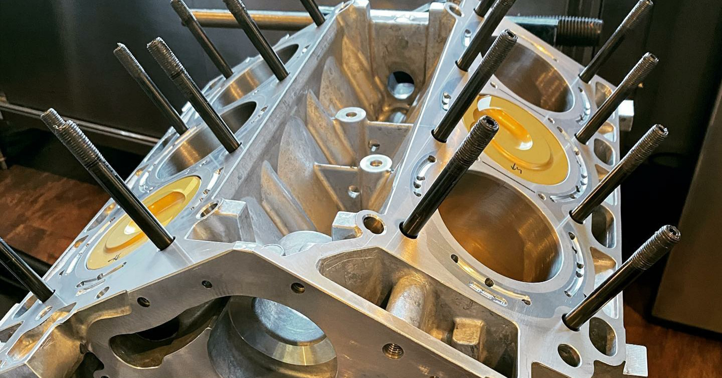
Brand new block, before it got sent out for the closed deck process:
Back from CSS with the deck closed off:
JE pistons before getting some Calico Coating love:
Skirt coating:
Thermal top coating:
These conrods are sexy AF! A set of Boostline conrods to push those pistons around:
Some ring gap measuring:
The centerpiece of all this…a Ford F-150 Raptor crankshaft:
Main bearings:
And some more lovely cross-hatch machining:
The King main bearings installed:
Checking end play:
And more clearance checking:
Completed short block:
Oil Pan, pickup tube and oil pump housing installed. Can’t forget the WPC treated Boundary oil pump gear installed inside that housing:
And some relentless engine assembly porn:
9And finally, arrival day! Thank you, Ryan, for all the great work to this point. I got it from here…
So, next step will be an engine stand sometime this week. Then it will sit for a bit until I tackle the intercooler dilemma on the current engine. I want to work all the bugs out on the engine I have sitting in the car now, so I’ll be mostly dialed in when the new motor goes in!
Stay tuned…
BUILD SHEET (not all inclusive):
New OEM Short Block
- CSS Closed Deck
- Boostline Connecting Rods
- ARP2000 Connecting Rod Bolts
- JE FS3 10:1 CR Pistons (CT3 sideskirt coating, Calico ceramic top coating)
- King XP Main Bearings
- King XPValves Connecting Rod Bearings
- OEM Ford Raptor Gen2 Crankshaft
New OEM Cylinder Heads
- Headgames Motorsports Pocket Port-R
- New OEM Valves (back-cut)
- ARP2000 Head Studs
- Titanium BeeHive Valve Springs/Retainers
- MLS Head Gaskets w/Integrated Fire Ring
And all the latest Ford iterations of accessory parts (chains, sprockets, guides, etc).
Lastly, I was dismayed to find that there is no way to remove the lower coolant pipe that sits in the valley between the heads with the engine assembled. It’s disappointing because I wanted to give it the same treatment I gave the upper intake coolant pipe…coated and insulated. Once the heads are on, because of the small branch-off pipe of the main coolant pipe, it won’t fit out of the heads. Ugh…well, it’s the one that got away…
EDIT: Turns out you CAN remove the pipe with the heads on, you just need to remove the knock sensor closest to the thermostat in the “valley”. Look here for more info on that.
UPDATE: December 17th, 2020…an early Christmas?
Things have been slow going, but I finally got the engine onto an engine stand…you might find it interesting, LOL.
Well here’s the fancy engine stand I ended up getting. Sunex 8300GB, 1/2 ton stand with oil drip pan. I wanted one with an actual gear-reduced crank handle because, well…I’m lazy, LOL:
Before mounting it onto the engine stand, I wanted to take care of the parts behind the mounting plate so it wouldn’t be an issue later. That meant installing the timing sprocket as well as the flexplate…
And for those wondering what this shiny orange flexplate is all about…I’ll let bpd1511 of the SHO forums elaborate. All the credit goes to him for getting that brought to market!
And even more entertaining is my engine hoist:
My Kubota BX25…how you like THEM apples? LOL
Got a hold of some metric Grade 12.9 (yes, it’s a thing) hardware. I custom-made some stainless sleeves to take up the slack in the larger diameter engine stand brackets. Makes for a super tight fit and no “slop”.
Everything has anti seize on it! Sleeves and all…
Getting it loosely mounted:
I like to get the center line of the crankshaft lined up with the center rotation point of the engine stand.
And mounted!
Rotated…just because I can…
And finally, all tucked away for the time being:
UPDATE: April 15th, 2021…just plugging away…
So for the past few months, I’ve been slowly completing assembly of the long block as it sits on the engine stand. Just slowly bolting parts up to it. I’ve basically bought 100% all brand new OEM FoMoCo parts for this and the goal is to have, in essence, a crate motor, ready to bolt up when the time comes…
So if you remember from earlier, I was pretty upset that I was not able to remove that lower coolant pipe without removing the heads. Well, it was buggin’ me so much, I decided to revisit this and see what I could find. It really happened when I was reading something in the factory manual about the knock sensors…
Turns out…that lower coolant pipe CAN be removed without taking a head off! You just need to remove the center knock sensor. Then, it’s a threading game weaving it between the intake runners to get it out. It’s a very tight fit and the pipe really wedges through it, but it will come out. It made me realize why the branch-off pipe is flattened in it’s center…so it can be threaded between the heads.
Now with it removed, I gave it the same treatment I gave the upper one…ceramic coat, pipe insulation and heat wrap…
It wasn’t a straight piece of pipe, so the bends were a bit tricky, luckily, the insulation tape did a great job of hiding everything, as well as helping keep everything in place.
The short section is for the branch-off pipe. It will be have to be slipped on once the pipe is installed because that branch-off pipe fits tight during installation.
Here is the pipe when finally installed back onto the engine. It was a royal pain in the ass to get that knock sensor back on with all that insulation on, but I didn’t let it discourage me.
Now, with that piece done, I pressed on with assembling more of the engine. Beginning with the timing cover and all the components behind it.
Using legit, FoMoCo TA-357 engine sealant (it’s what is recommended and I’d stick with it, it’s been said other stuff can cause the oil to foam up…no bueno) and a DeWalt DCE560 caulking gun (this made life way easier)…
…I applied sealant as recommended by the manual. It goes on a bit thicker at places where the engine side has seams (oil pan to block, heads to block, etc.).
Once that was done, started installing a few other parts.
A bunch of other OEM components to include the crank pulley and front main seal. Here’s a long boring video of some engine assembly (LOL).
I also installed an Improved Racing ENV-131-T6 200deg thermostatic oil cooler adapter. It’s got -10AN IN/OUT lines. I will be installing an external oil cooler as well as transmission cooler on this thing when it’s finally sitting in the engine. Also, installed the Amsoil EA017 oil filter again. Love the larger size and it’s a great quality filter.
UPDATE: April 25th, 2021…trouble in paradise.
Noticed big problems a few weeks ago, but just got it addressed and installed today.
So…it came to my realization when I attempted to install my valve covers on earlier in the month that there was some fitment issue. For some reason, the composite valve cover would not seat properly around the high-pressure fuel pump (HPFP) pedestal.
After removing it and conducting some investigations, it dawned on me that I may have a pretty serious issue at hand…the pedestal for the one I have was the incorrect one. Though these heads were low mileage heads when I had Ryan work them, they were still off of a 2013 3.5L ecoboost. This build was all based off of a 2015 installation. Now, that isn’t TOO much of an issue as the right hand head part number was identical, but it was the left hand one that was different. See, in 2013 the valve covers were aluminum:
And in 2015, Ford updated those to composite:
There are a few differences. Externally, the EVAP inlet tube sits higher up on the newer valve cover. And there is also an extra valve cover bolt in the area where the HPFP sits. But the real issue was internally. Functionally, the heads are no different between the years, however, the pedestal for the HPFP has a slightly different profile as well as a clocking notch machined into it on the newer heads. Don’t ask me why Ford only changed the left side head and not the right side head…I’m sure there’s a reason, though.
If you notice, the pedestal has a different height shoulder, and the higher shoulder on the 2013 is what was digging into the 2015 valve cover…this was a pretty major dilemma. Was there anyone to blame? I can’t blame Ryan, he showed me these heads before he got them to get my blessing and I have to say, he’s an F150/Raptor ecoboost genius but hasn’t done as many transverse versions, and the subtle differences can be a lot. I wouldn’t expect anyone to know every tiny difference between every model and year between those models. So what are my options:
- Change to a newer style. This was out of the questions as I had headwork done on these heads…too much trouble and cost.
- Change the valve cover to the aluminum ones. I didn’t like this option for a few reasons. The newer configuration was slightly different on the right-hand cover, but the left hand cover had an external PCV system on the older ones and I didn’t want to change to the older style covers, though this was a viable option, it would be my last resort.
- Just use a pedestal off a newer model. This wasn’t a good option for a few reasons. One, it’s impossible to get this part by itself new, you’d have to go to a junkyard and find one. Two, more importantly, this part actually holds down the camshaft and since there is no sleeve bearing to fit, it has been line-bored to fit this camshaft assembly. I would have to remove a bunch of stuff and have the entire assembly re-line-bored. No go on this option…
- Machine the existing one to match the newer style. This was the best option and the one I used. It allowed me to reuse the existing pedestal and after very careful and in-depth comparison between the two styles, it became clear to me that Ford simply shaved the shoulder down and added the notch in order to ensure they would never be clocked incorrectly. I decided to just go for it…
This is how it started out…
Took it to a machinist friend of mine who put it on the mill to get the shoulder down.
As you can see, there turned out to be some porosity in the casting, and at probably the worst place. We made sure to machine the radius into it to minimize any issues. I am pretty confident it will be just fine. Onto the notch…had it machined out as well.
And finally getting it installed back onto the head.
Since the older heads didn’t have that bolt hole, it could possibly cause issues, so I decided to at least add some sealant at that point. Again, I’m pretty confidant it will be just fine.
I wanted to also add that, before I installed the valve covers, I did remove some of the unnecessary studded valve cover bolts. They get in the way I feel and I’ve seen them chafe wires as well, so I figured out which ones weren’t needed and I replaced them. Similar to the one that I replaced during the fuel injector installation.
Here is the part I used, I think I used about 7 total.
And here is a brief video showing how I replaced them. Also shows the valve covers being installed, even though…at this point in the write-up, I haven’t gotten to it (video was edited after much of this was done).
This is the valve cover bolt hole that will not be utilized. Relying on the sealant instead. Fingers crossed.
Definitely not the best thing to happen here, but I’ve got warm and fuzzies that this will work just fine…
After I finally got the valve covers on, I moved onto installing the spark plugs and coil packs.
UPDATE: May 25th, 2021…I love gooooooooooooollldddddddddd…
So i started doing some insulation work while I also continue to install all the OEM exterior engine parts that would make this into my crate motor. Started with the turbo oil drain lines:
To achieve this, I used some silicon-coated sleeving from McMaster:
But the sleeving isn’t enough for me…lol.
Next up was the wiring harness for the injector rails.
With the harnesses complete, time to move onto the fuel rail assembly and install!
In case I didn’t mention it before, those are brand new XDI 50% injectors. Going from the 30% Gen1 injectors to the newer 50% Gen2 style.
For the fuel rail/injector installation process, check out this link.
As you can see, I have the ignition coils installed. I decided to return to OEM ignition coils on the advice of Ryan as well as hearing how the MSD coils have a history of failing. The OEM ones provide more than enough spark, no need to fix whats not broke. I did like the red “look” though. I am still using the Brisk RR14YS plugs though, I really like them.
So I started insulating the turbo oil feed lines as well.
I removed the OEM flexible insulation section and replaced it with a section of DEI wiring insulation. The hard pipe section I insulated the same way I did the drain lines. Silicon-coated sleeving then gold reflecting DEI tape.
From there I moved onto installing the exhaust manifold studs. I dislike the OEM ones because they seemed to rust through pretty bad and then can become difficult to remove if needed.
So I decided to go with some ARP stainless steel ones. These are actually ARPs high strength stainless alloy studs and nuts, so you can apply more torque to these than standard 18-8, 304 or 316 stainless.
What I also decided to give an additional layer of insulation to was the heat shield for the left-hand turbo. It protects the wiring between the turbo and the engine block. It was just plain aluminum before this.
Here’s how it sits as of now, with the heat shielding done up to this point as well as the exhaust manifold studs installed.
Alternator…