Wow, well this was a project that took a VERY long time to complete…I’d say roughly 2 years from date of purchase to finally injecting methanol. It also took quite awhile for me to get this write-up completed. Lot’s of reasons, but mostly just got busy and was sidetracked by so many other projects. And life happens…
- Overview
- System Selection
- Rear Hatch & Tank Installation
- Intake Manifold
- Gauge Installation
- Controller Wiring & Installation
- Testing
Overview
Finally, here it is…an Aquamist methanol injection kit! I tout this company as often as I can because I’ve felt they are leaps and bounds ahead of the pack in regards to Water Methanol Injection (WMI). Lot’s of reasons, but mostly because it’s legitimately the most advanced, well thought-out and thorough kit available.
So before I get into specifics of the install…I wanted to answer a question I often get, “Why did you choose this particular system over all the others that are out there?” Well, that question can be answered in my other post discussing just that. It’s a long read, but can be pretty informative so please feel free to check it out. If nothing else, the videos are pretty indicative of why this system is better than others out there. That isn’t to say the others don’t work, I simply feel the technology in those “other” kits hasn’t progressed comparatively in relation to where the automotive industry is at these days.
Admittedly, purchasing an Aquamist kit can be slightly intimidating. I understand that. Lot’s of options and the website could probably use a bit of help. It didn’t help that there had been no 3.5L EcoBoost application done before using one of their systems. So some of this, particularly the wiring, required some experimentation and frequent contact with their support, who was a tremendous help. Hopefully, this write-up will help you skip some of that should you choose to go this route.
The kits can rack up in cost as you add more features, and I pretty much went with all the bells and whistles (translation…it was expensive), but the cost comparison for a kit with, maybe, a few less options is actually very comparable to many of the kits out on the market and in some cases, less expensive. Combined with the fact that this is a far superior product (you get what you pay for), the cost is reasonable, IMO. Below is an old chart, but still relevant, comparing the costs from some for the more well-known competitors.
System Selection
Getting what you need can be a bit tricky. You’ll have to know what your goal is, both estimated power as well as how you plan on using the system. Do you want straight methanol or should you do a mix? Do you want to go direct port injection or stick with a traditional single/dual injector setup? Do you want to use check valve jets or not? These are some of the questions you should ask yourself.
When you start out, the first question you want to ask yourself is…do you have a direct injection engine? This will dictate whether you need to purchase an HFS3 or HFS4 system. They are virtually identical except that the HFS4 is setup and programmed for the unique requirements of a direct injection engine. What is a direct injection engine and how do you know you have one? Well, since you’re shopping around for methanol kits, it’s highly likely you’re a gear head and would hopefully know enough to be able to identify this. But if not, the easiest method is to look at your engine and see if you have a High Pressure Fuel Pump (HPFP) bolted to the top of the engine somewhere. On this platform (Explorer Sport, SHO, Flex, MKS, MKT, PIU, PIS), it’ll look like this:
A HPFP basically takes fuel from the tank (there’s a Low Pressure Fuel Pump, LPFP, in the tank) and raises the pressures to a few thousand PSI and sends that fuel to the injectors which are firing directly into the combustion chamber, post-intake valves. This allows for better fuel economy and higher power output with less fuel.
One drawback of direct injection can be carbon deposits that build up on the backsides of the valves. This buildup was usually “cleaned” by the fuel the was injected via the port before direct injection was introduced. A direct port injection methanol kit will actually help with this and “clean” the backside of the valves. An added benefit…
Anyway, in the case of this platform, it does have direct injection, so I went with an HFS4 system. This is where I started the journey
Selection of the basic system
The HFS4 purchase page has some options you’ll need to entertain. It starts out pretty self-explanatory.
- What color do you want the gauge to be? I picked blue, but they’ve got red (it isn’t amber, but a red). I felt the blue would go with the interior night lighting of the car better than red, but the choice is yours.
- What size jets do you want? This selection will get you any three (3) non-check valve (NCV) jets that you want. If you leave it blank, you will get a 0.8mm, a 0.9mm and a 1.0mm NCV jet. This is a standard selection and if you spring for the direct port add-on kit, you will be selecting additional jets, but you will still get these three. It’s sort of standard issue with the kit. These are jets I did not actually use since I went direct port, but they come with the kit anyway. Remember…you get NCV jets as standard. If you don’t go with a direct port kit and want to just have three jets placed in other places (i.e., one for each turbo outlet, then one post-IC), you can use these and buy some regular check valves that are installed inline slightly before each jet (in the example above, I’d get three of those check valves, one for each jet) or you can spring for the more expensive check valve (CV) jets, which have the same 15psi check valve built into the jet itself. Even if you go this option and order CV jets you will still get those NCV jets with your kit. The benefit of the NCV jet is that the check valves are cheaper than the CV ones, keeping cost down. The benefit of the CV jet is that the methanol stops right at the nozzle tip. The farther back you have that check valve, the more residual methanol left in the lines that can be drawn into the air stream via vacuum. So the closer to the tip of the nozzle, the better, hence the benefit of a CV jet. I knew I wouldn’t be using these jets, so I just left it blank. Check out this part of the write-up to see how nozzle size is selected.
- Is it UNIVERSAL or MODEL SPECIFIC? Aquamist does offer kits already bundled and assembled with everything needed for some specific platforms. They usually come with some brackets intended for that platform as well as coming preset and with the required jets. Everything you’d need. But don’t see your car in that list? No worries, they’ve got you covered. Since this platform wasn’t on the list, I just selected “UNIVERSAL”.
- Estimated HP? This is were you’re going to have to be realistic about where you think you may be going in the future. It will dictate the size of jets, etc. This is wheel horsepower, BTW. 500-550awhp is where most people modifying this platform tend to achieve. This is, generally, the limit of what the stock engine/transmission can take before things start to break. So a lot of people stop at that power level. When I initially sourced the kit, it’s the number I went with. I ended up wanting larger jets, so as I went on with the install, I ended up having to purchase those larger jets separately. So unless you want to order more than once, really know where you want to go. I’ll talk more about jet selection in a second.
- Model of car? Here is where you list your make/model. Even though Aquamist doesn’t have kits available for all cars, they do have wiring diagrams for many additional vehicles and would send you one via email based off this information. Since there wasn’t a kit for this platform, I used the generic wiring diagram that told me what signal each wire required. I then did my own research using Ford wiring diagrams for this model and made my own. I updated the generic drawing and sent Aquamist what I discovered and they then made one based off that data…so thankfully, there should be a wiring diagram for 2013+ Explorer Sport, SHO, Flex, MKS, MKT as they are all similar.
- 3000cc pump? This is for really high-power applications sending lots of methanol. It requires an entirely different Fast-Acting Valve (FAV) setup so unless you are running high-power, stick with the standard pump (it’s 1600cc, I believe). I ordered the standard pump…but I ended up eventually switching to the larger pump, because I’m always wanting more, hahaha
- Quantity? Of course, you probably only want one kit, LOL.
What’s in the box?
Now that you’ve selected the basic kit, below is what comes in the box. This is important to know in case there are additional fittings and accessories you want, should you choose to do some modification or customize your system a bit. I know I did:
Moving onto the direct port add-on option
So, because you’re like me and want the latest and greatest, you’ll want to go direct port injection. Why? Well, direct port injection delivers perfectly balanced octane and cooling benefits. It solves the common distribution issues associated with single or dual nozzle WMI systems by placing a nozzle in each intake runner and allows you the ability to precisely meter how much fluid is delivered to each cylinder. Distribution is never perfect from simply a single, post-IC nozzle as is found in many generic setups.
Even the tiniest spray droplets have mass. Inertia carries most of these particles to the cylinders farthest away from the throttle and delivery ends up being unbalanced. When the post-IC nozzle is small, the variance per cylinder is not large. However, with larger nozzles and more flow, it becomes a far more critical issue. Aggressive tuners are often frustrated by insufficient protection “here” and a combustion-quenching over-saturation “there”. The only safe response is to dial back the boost/spark timing to satisfy the most vulnerable chamber. In this case, you’re basically tuning to the weakest cylinder, which doesn’t allow you to maximize the potential. Meanwhile, direct port guarantees that each cylinder receives exactly the same spray volume.
Plus…in a direct injection engine, the methanol cleans the backs of the intake valves, which are notorious for carbon buildup.
Even Bosch/BMW are implementing this technology as it’s being found on many stock automobiles.
Now that you’re sold on the merits of it…what do you want to get? Well, Aquamist offers it as an add-on bundle package. Here’s some info on the selections.
- What size jets do you want? This is where some calculations come into play and you will need to decide on a few things. Check out the next section for this one.
- What type of jet connection and arrangement are you looking for? This option allows you to select what type of hose connection you want (a barbed hosetail or compression fitting) as well as how much of a nozzle extension your looking for. This option will extend the nozzle into the runners a certain distance and can be useful if your installing this into some thick material. So 95% of the time, you’re going to want to go with the compression fitting. Aquamist used to do the push-to-connect style, but I think they had some issues with them, so they use the hosetail and compression type. The compression is the most secure…stick with that one. As for the nozzle extension, for this application, I went with 5mm for the direct port injectors. When you get to the portion of the install into the runners, you’ll see how much it protrudes into the runner. I went with the 10mm for the post-IC nozzle as I had to stack a few adapters up to get it to the correct size. Below are some photos of the Aquamist nozzle types. They have a lot they offer…much of it not listed on their website…so if you have questions…reach out to them.
- What size inlet for the hex manifold do you want? Only 2 options here, 4mm and 6mm. I kept it the same size as the pump outlet (since, in this setup, will be feeding directly to the manifold inlet) and went with 6mm. I know it says “3rd party”, but all the Aquamist fittings will work. This option refers to inlet of the hex manifold. It’s mostly a moot point as most current users will want the FAV and flow sensor attached directly to the manifold. This allows for the most compact package and is what I am doing. But, in case you really wanted…you could have this manifold separate from the FAV and flow sensor assembly…the choice is yours.
- What is your engine configuration? This is where you select how many cylinders your engine has. In this case it’s 6. You can get the hex manifold in a “V” setup for only 8-cylinders and up. But you can contact them and they can tell you otherwise. Again, there are so many other fittings they offer that they don’t even advertise on their website, it may benefit you to contact them if you are curious if a particular arrangement can be requested. Their website is very incomplete…it is their Achilles heel if you ask me.
- Quantity? Of course, again, you probably just want one kit.
Nozzle/jet size selection
Here are the variables to consider when making calculations for the nozzle size you want to use. I ended up creating an excel spreadsheet that did most of the calculations for me.
- Choosing water/methanol flow for your application:
- 100% water: 10-15% water/fuel ratio or 0.5-1.0cc per WHP
- M50/W50: 15-20% MW/fuel ratio or 1.0-1.5cc per WHP
- 100% methanol: 20-25% methanol/fuel ratio or 1.5-2.0cc per WHP
- Selecting the correct jets for the required flow:
- Calculate the “true” pressure by subtracting your expected maximum boost pressure from the 160psi pump pressure.
- Select the jets from “true” pressure and flow requirement from the chart below.
- Always pick the next size up or allow 10-15% for more headroom. I usually just run with the “next size up” concept.
But to make your life a bit easier, I ended up creating a calculator to help simplify the selection for you. Simply take the value you get for the Individual Port Nozzle and the True Pressure and find where that intersects, then select the closest higher nozzle size.

For example, a calculation has you at a true pressure of 142psi and a port nozzle flow rate of 167cc/min. That would place you between the yellow (0.4Cmm) and the green (0.5mm) line. So green (0.5mm) is the way to go on this injector. And if you are running a post-IC injector, nozzle size should be double the flow of the individual jet. So that is 333cc/min, so that’s between the blue (0.6mm) and red (0.7mm) line. However, since it gets very close to that red line, I would personally jump to the pink (0.8mm) line. So you’d get six 0.5mm jets and one 0.8mm jet.
What’s in the box?
So you got your jets figured out? Here’s what’s included in a direct port bundle for a 6-cylinder.
- 1x multi-port hex manifold
- 6x CV jets with compression fittings
- 6x 1/8NPT jet adapters (one per cylinder)
- 1x CV for post-IC jet
- 1x 4mm to 1/8BSP compression fitting for post-IC jet (hex manifold output port)
- 4mm high temperature PTFE hose
What the hell? Plastic tubing?
So, I often get asked why I would use plastic tubing. I mean, Prometh/Livernois makes a sick looking stainless steel distribution setup for direct port injection, right?
Although Prometh is a big player in the methanol game, in this instance, I don’t believe they got it right. There are a few reasons why “plastic” tubing is a much better option than the stainless version others may like to use. One of them being the most important, IMHO.
- First off, it isn’t simply plastic…it’s Extreme-Temperature PTFE Semi-Clear Tubing. This stuff is good to 500 degrees Fahrenheit before it even starts to deform. Yes, stainless lines will take much more heat than that before it becomes damaged, but if you’re hitting engine bay temperatures in the 500 degree range…there’s something else going on and you probably shouldn’t be in the car.
- Secondly, it’s simply way easier to manage the lines when using PTFE. Whether sizing, trimming, replacing, etc. It’s relatively inexpensive and doesn’t require tools or special fittings to utilize. Push-to-connect fittings aren’t ideal, I’m aware, and some systems still use them, however, much of Aquamist’s new hardware utilize a compression fitting…it isn’t going anywhere, nor are you worried about a plastic push-to-connect fitting leaking any longer.
- Lastly, and really most importantly, is the mitigation of heat soaking the methanol. You’re not always in boost and when just driving reasonably, not in boost, the methanol isn’t typically being injected. That means you have methanol just sitting in a line absorbing the surrounding engine bay heat. Keep in mind, methanol boils at about 150 degrees Fahrenheit. You’re engine bay will certainly hit that temperature and those stainless lines are just sitting there absorbing all that heat, transferring it to the methanol. You don’t really want to boil your power adder. At a minimum, it reduces the effectiveness of the liquid, and why would you want to do that when you paid hard-earned money? LOL.
But the stainless steel hard lines sure look pretty, don’t they?
BTW, on the topic of PTFE line…Aquamist supplies quite a bit of it and you’re more than welcome to order additional if needed. But it can take some time to come from across the pond (all this comes from the UK). McMaster offers it and it arrives quickly.
Now, let’s move onto actual installation!
Rear Hatch & Tank Installation
I started my installation of the kit in the rear hatch area. It was easier and it would intrude the least while I was having to drive the car as I knew this kit would take some time to finish (who knew it would be almost 2 years?). But before I began installation, there were a few changes I wanted to make, particularly to the wiring harness.
Wire harness preparation
I’m always looking to improve on things and this is an area where I felt I could. I imagine the Molex connectors work just fine and I’m sure were used to keep the cost of the kit down so there is no need for the following improvement. However, if this harness were to see the outside of the vehicle for some reason and you wanted it weather-resistant, this would be a worthwhile endeavor. I did it anyway because I love high-end electrical connectors! LOL!
Pump connector
Parts needed for the pump connector:
- Pin Contact PN: 0460-202-16141, Qty: 2
- Receptacle Connector PN: DT04-6P, Qty: 1
- Receptacle Wedgelock PN: W2P, Qty: 1
- Plug Wedgelock PN: W2S, Qty: 1
- Plug Connector PN: DT06-2S, Qty: 1
- Socket Contact PN: 0462-201-16141, Qty: 2
Float switch connector
Next connector on the blue harness to convert is the smaller 2-wire float switch. This was also a small Molex connector, but I decided to go with a weather-resistant JAE connector.
Parts needed for the float switch connector:
- JAE MX1900 Female Terminal PN: MX19P10K451, Qty: 2
- JAE MX1900 2-position male pin connector PN: MX19004P51, Qty: 1
- JAE MX1900 2-position female socket connector PN: MX19002S51, Qty: 1:
- JAE MX1900 Male Terminal PN: MX19S10K451, Qty: 2
Water tank/pump installation
I began the actual installation of components with the water tank. I initially purchased a different, generic, water tank with the intent of installing it in front of the driver’s side front wheel, behind the bumper. I was going to have this elaborate fill system and thought it would be great. But upon further work, I realized going the more traditional trunk installation method would be better, and it doesn’t look bad, either. It does take up room in the back, but I never carry any loads with the car anyway. The Aquamist-specific water tank is an additional purchase and they have a few options to select from. I ended up going with the 10L tank with bracket.
But because I can’t leave anything alone, I decided to make some changes here as well. I wanted the bracket black and I needed to find a way to bolt it to the x-brace I had installed in the rear when I deleted the third row seats.
For the bracket mount, I used some standard 1″ angle iron that I would weld onto the x-brace. This would provide for a flat spot to bolt to since the x-brace was tubular in shape.
I then sandblasted the tank bracket and drilled corresponding mounting holes on the top flat section
Since the x-brace comes unfinished, raw metal, it was easy to prep for welding the angle iron bracket-mount to.
I then mounted the pump to the bracket and used some sticky back foam to help minimize chaffing due to vibration of the tank on the bare metal bracket. It would also keep the noise down as it jostles around.
It is ideal to have the pump lower than the tank that supplies it as it helps to keep the pump primed simply from gravity. It’s not necessarily an issue in any other configuration, this is just one of those small things you can do to increase efficiency of the pump. The bracket that comes with the tank is designed for this, so that was easy.
With test fitment of the bracket on the angle iron completed earlier, it was time to install the bracket to it. Since the bracket would not be able to be installed in the test-fit configuration when finally installed, I had to raise it somewhat, in order to clear the pump and floorboard properly.
Parts needed for the stand-off of the tank bracket:
- 316 Stainless Steel Unthreaded Spacer PN: 90138A730, Qty: 2
- Super-Corrosion-Resistant 316 Stainless Steel Socket Head Screw PN: 92290A341, Qty: 2
- 316 Stainless Steel Split Lock Washer PN: 94241A540, Qty: 2
- 316 Stainless Steel Washer PN: 90965A170, Qty: 2
It was around this time that I wanted to increase my systems capacity and decided to switch to a 3000cc pump instead of the 1600cc one I had initially ordered. I also ended up having to switch the internal spring from a 160psi one to a 200psi one. Going from a 1.3gpm pump at 160psi to a 1.6gpm pump at 200psi is what allows for the increase from 1600cc/min to 3000cc/min.
Next was getting all that methanol to the engine. Aquamist provided 6 meters (about 18′) of the 6mm stuff and it was barely enough. If you need more and didn’t order it with the kit, you can also get it from McMaster, as mentioned earlier. One thing I did want to do, since I was going to run the line under the vehicle and exposed to the elements, was to line the hose with some insulating silicon sleeving. This comes in either 10′ or 50′ rolls so, you’ll have bite the bullet and have some left over if you want one single clean run without a break. Although, you could buy two 10′ sections and heat-shrink the seam…that’s one way to save around $20. I just like having the extra for other things if I need it or if I mess up somehow.
- Electrical-Insulating Tube Sleeving PN: 2573K241, Qty: 50′
But before we run the hose underneath, I got a little extra fancy and instead of just drilling a hole in the body and using a grommet (which would be just fine to do, BTW), I decided to use some pass-through, push-to-connect, stainless steel bulkhead fittings. Yes, they actually make those…
- Stainless Steel Push-to-Connect Through-Wall, 6 mm OD PN: 7610N194, Qty: 2
It creates a more positive pass-through with no chance of chafing or rubbing. It also looks much more clean, IMHO. I used some stainless bumper washers to help hold the carpet down as well.
So It’s critical to vent the tank somehow. The pump will create a vacuum on the tank while it’s in use or heat will create a pressure situation when in a hot car during summer. Venting will mitigate this, however, the issue created when venting into the cabin is the possibility of toxic fumes…no bueno! The answer…vent to the outside of the vehicle.
This all starts with the tank vent accessory (yes…an additional cost) from Aquamist. But I wasn’t a huge fan of the plastic push-to-connect fitting. It is secured to the plastic tank cap with a slim jam-nut underneath.
So, as with everything I do, I improved it bit and went with an all-stainless version. It is a non-standard fitting as it uses a BSP straight-thread instead of an NPT tapered-thread…so the fitting was a bit pricey and took awhile to arrive, but I am glad I went with it.
- Stainless Steel Push-to-Connect Tube Fitting for Air&Water PN: 51065K748, Qty: 1
So once it leaves the inside of the vehicle, you don’t want it just open and wild as there is the potential for something to eventually block the hose, so it would be beneficial to have a breather vent of some sort. Since the exterior of the pass-through fitting is also push-to-connect, I used the below parts to create that breather vent.
- Stainless Steel Push-to-Connect Tube Fitting for Air and Water PN: 51065K726, Qty: 1
- Precision Extreme-Pressure 316 Stainless Steel Fitting PN: 48805K72, Qty: 1
- Corrosion-Resistant Breather Vent PN: 4456K11, Qty: 1
After sleeving the entire hose run and securing it to the undercarriage safely and out of the way of anything that may cause issues, it comes up near the rear of the firewall and tucked away for the time being.
A few photos from the back side of the tank installation:
Pump and tank level (Trunk) wiring
As for wiring and connecting this particular harness from the pump/float switch to the controller, I began by finding a place to mount the fused 30A-relay. This would form the basis of how long the wires would ultimately end up being and how they would be routed.I ended up placing it behind the panel for the rear area on the driver’s side rear wheel. There is a small hold-down bolt already there and just used that as the mounting point for the relay bracket.
There specific wires that would be run were:
- Pump wires: this is the 12ga positive and negative wire going to the pump itself. These were connected through the Deutsch connector, with the positive being connected to the 30A relay OUTPUT and the negative going to a ground on the frame somewhere. I used a self-tapping screw with a washer and ground it here:
- Float switch connector wires: This 2-wire pair was simply connected to the connector next to the relay. These two wires, along with the two relay control control wires, become part of the blue cable with the 4-pin RJ-45 connector that would be run towards the glove box.
- Relay wires: The 12ga positive output connects to the positive wire of the pump and the 12ga positive input will run alongside the blue cable to a constant, unswitched 12VDC power source. This is addressed here. The two small gauge control wires merge with the two small gauge float switch wires to become the blue cable mentioned above.
Here you can see the prepared-harness mounted with the pump and float switch connector. The issue with the pump connector is that, with the location of the relay, it was too short to reach the pump itself. So I had to make an extension.
I could’ve removed the connector and done some butt connectors, but felt it would be more clean and professional to simply make a short extension that I can easily connect. I used the same connections as was used when making the pump connectors and below is another breakdown assembly of what is used along with another parts list:
- Pin Contact PN: 0460-202-16141, Qty: 2
- Receptacle Connector PN: DT04-6P, Qty: 1
- Receptacle Wedgelock PN: W2P, Qty: 1
- Plug Wedgelock PN: W2S, Qty: 1
- Plug Connector PN: DT06-2S, Qty: 1
- Socket Contact PN: 0462-201-16141, Qty: 2
The relay in this harness is a fused 30A automotive relay and is designed to protect the pump should there be a short or a pump failure. The fuse that directly connects to the relay is a perfect combination. However, the only issue here is where I placed the relay. Once the panel is back on, the relay will be inaccessible and thus the fuse, if it blows, will not be easily reached. So to address this, I simply extended where the fuse would go in order to access it easily.
To allow for easy access once the panel is reinstalled, I wanted to run the fuse directly underneath the small plastic cover that gives access to the rear shock tower nut.
In order to accomplish this, I used a remote fuse holder and simply stuffed it under that cover. Below are the parts needed to accomplish the fuse holder setup.
- MP280-2S-12-Way Kit, Qty: 1 (with MP280-SKT2 Socket and MP280-SL1 Insulation Seal)
- MP280-ATM Cap, Qty: 1
As for the pump power wire, I didn’t get any photos of it, but running the long power wire and blue harness was done by lifting up the door sill panels in the rear and front driver’s side. When lifting these sill panels up, you can run wires from rear to front easily.
I then used the large zip-tie method to feed the wires through the sill area. It brings the wires up within the dash area near the pedals. The blue connector was run across to the other side to the glove box area and the power wire for the pump/relay itself was tapped into a direct , unswitched 12VDC battery source that is found in the body control module (BCM). I got somewhat creative here to keep from having a large gauge 12VDC wire running all the way from the battery and through the firewall.
On the BCM is a large connector that houses the 8ga power wire from the battery. It is the fused 100A source. Here it is disconnected from the BCM:
If you cut the zip tie at the base of the connector, then gently pry up the retaining clips and take apart that plastic housing, you are left with this:
This is where I would tie the 12ga pump/relay power wire to.
I used a barrel crimp I had in my terminal kit that was big enough to bundle the wires together at the exposed area of the 8ga power wire.
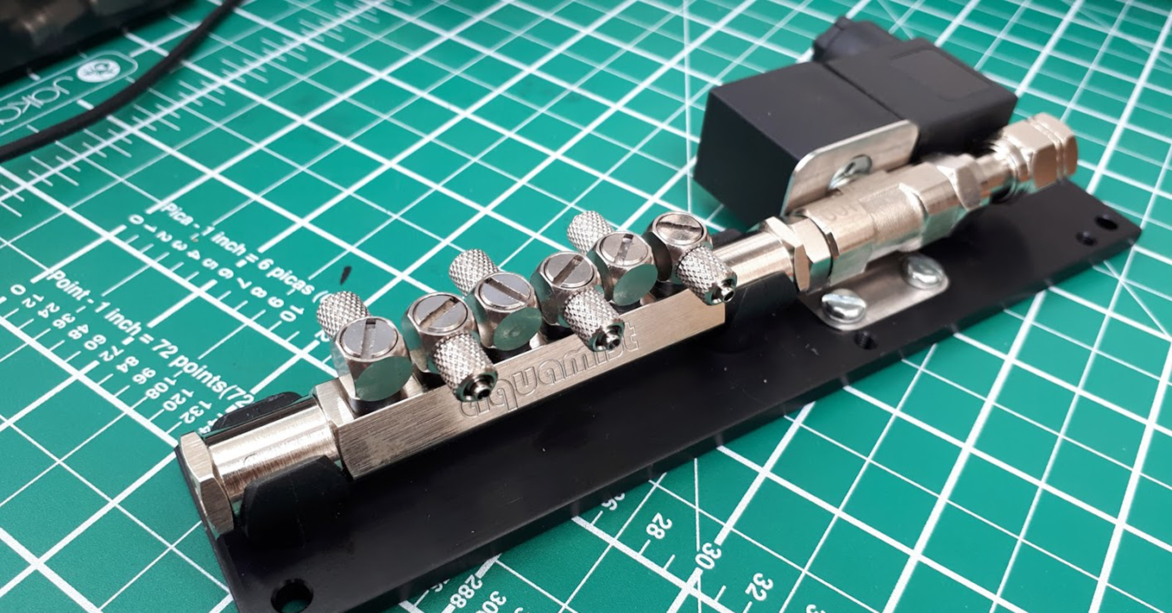
Intake Manifold
The next component on the list to take care of was the actual intake manifold. Again, I like keeping downtime to a minimum so I ended up purchasing a brand new one from Ford. First step in teh process was doing everything on the bench.
- Intake Manifold PN: DG1Z-9424-A
Methanol manifold mounting
One of the first things to do was come up with a way to mount the flow sensor, FAV and hex manifold assembly. I wanted to place it right above the intake manifold as it would keep the methanol lines short. I ended up using 3 mounting points for the bracket I made out of aluminum. 2 of them were the mounts for the engine cover and the third was the hold-down bolt for the MAP sensor. The piece of aluminum I had just laying around. It didn’t need to be big so it was a scrap piece leftover from some other job. The stand-offs and hardware I got from McMaster again. After final install, I ended up shortening up the stand-offs, so the following parts are the final, shorter ones I used, but the next few photos are of the initial longer ones.
Parts list for final version:
- Rear Spacer PN: 92320A902, Qty: 2
- Rear Bolt PN: 92290A338, Qty: 2
- Rear Lockwasher PN: 94241A540, Qty: 2
- Rear Washer PN: 93409A134, Qty: 2
- Front Spacer PN: 92320A665, Qty: 1
- Front Bolt PN: 92290A180, Qty: 1
- Front Lockwasher PN: 94241A520, Qty: 1
- Front Washer PN: 95211A140, Qty: 1
In order to keep the bracket from flexing, I placed a bend on the backside of the plate. This would keep the aluminum from rigid and in-place.
Jet installation
After the bracket was mocked up, the next part to tackle was actual installation of the jets. What makes the Aquamist kit so great, IMHO, is the way they install the jets. Custom welded bungs could be used if you wanted to go that route, but they are not needed, and in fact, their jets can be used even on thin metal. Their jet adapters are designed to give the amount of tension needed and are extremely simple to install. They even offer the proper tap if needed. Though it is a standard 1/8NPT tap, they have one that can provide the proper depth.
Tapping with an NPT tap can be tricky. Since it is a tapered thread, it has to go a specific depth in order to provide the amount of thread engagement required. If you don’t go deep enough, you won’t get enough, and if you go too deep, you will never be able to tighten the adapter down properly, if at all. Below is an indicator of where on the tap you’d need to be when tapping.
The location of the jet, especially on the backside of the manifold, was dictated by the middle (cylinder #2) EGR valve mount location. It is the extra thick rib of material. Some other methanol kits grind this part down. This is just unnecessary and way too much work. Plus it looks like shit. I decided to tap the jets at an angle on the back side, ensuring that they still point to the center of the port as much as possible. Using the jet adapter makes this quite easy.
Here are some examples of proper jet placement when using different mounting methods. Whether using a jet adapter, a welded bung in the manifold, or both.
As for how deep the jet should be installed, this extension into the port is actually ideal, according to the engineers at Aquamist.
Hose configuration
Once the jets are installed, it’s time to get the hoses measured and cut. It is important to know that the hoses DO NOT need to be identical in length. Since these are CV jets, the hose is always charged right to the jet, so hose length is unimportant. Below are some photos of the hose routing and mock up.
While I was at it, I wanted to create some additional sources to access manifold pressure. I had converted to a manual TialSport BOV and had been using the rear vacuum line as a vacuum/boost source, but I wanted to make the line more direct and shorter. So I tapped and threaded 2 access ports. One for the BOV and one for future use if needed. It would be a pain to do this later on as drilling would cause chips to fall into the intake manifold unless I completely removed it again and I wanted to avoid that.
here you see the 2 fittings I used. I will list them below in case you’d like to know what I used, but I ended up changing them out after I got the manifold powder coated as I wanted to avoid using plastic fittings.
- Push-to-Connect Tube Fitting for Air PN: 5225K725
- 316 Stainless Steel Threaded Pipe Fitting PN: 4452K122
Powder coat
Finally, I’ve always loved the look of the Acura Integra Type-R bright red, textured valve cover look and wanted to emulate that here. So I began the process of prepping for powder coating.

Here are some shots of the threaded holes without the jet adapters installed and also where I began taping the manifold off for powder coating. Since this was going to be a showpiece as well as functional, I wanted to show it off a bit.
The black duct tape I used was temporary in order to block off some critical surfaces while I sandblasted the manifold. This black duct tape was replaced by specific powder coating tape. I also used some silicon caps to block off the coolant passage tips and silicon plugs for some of the remaining openings. I like to do all powder coat prep myself as I’ve had some bad experiences having the shop either powder over something I needed exposed or not coating what I needed coated. TBH, this keeps cost to a bare minimum as the shop I go to simply charges me for the powder process and not prep work. They usually appreciate my work, LOL.
Some images of the finished powder coating job and installation of the jets into the ports below. As you can see the places that are bare aluminum are what I taped off. It is important to not powder over something that will see significant pressure, like beneath a bolt head/washer. Sometimes, powder can crack when a bolt is torqued over it (not to mention, you can’t get a legit torque value if the bolt doesn’t contact bare metal. Once it begins to crack, it can sometimes spread. I also do some final sanding when all the tape is removed to ensure there is no powder coat “slag”.
Here is a video I made of some post-powder coating “cleanup” I do whenever I get parts sent off. This video is from a Harley-Davidson build I did, but it showcases the amount of work that should really go into a powder coating job.
Final preparation
Installation onto the engine
After completing installation of all the components onto the intake manifold, I installed it back onto the engine. Here is a video of the install. It was actually part of a larger collection of videos I made when I installed a number of parts onto the engine, to include upgraded fuel injectors.
A good shot of the final installation of the intake manifold onto the engine with the methanol kit installed.
Gauge Installation
Next up was installing the gauge. The gauge for the Aquamist kit serves a few purposes and is invaluable for observing what is going on with the system during operation. It shows when the system is flowing as well as how much, by way of an LED bar graph. It also shows when the level is low in your tank and having the ability to easily turn the system off. The potentiometers are used to scale bar graph as well as setting the limits for failsafe that Aquamist utilizes.
I wanted my gauges mounted on the a-pillar, but you can place it anywhere you have room, limited only by your creativity. I had initially purchased a gauge pod that mounts in the vent from Aeroforce Tech. After purchasing this and attempting it the install, I didn’t really like how it looked as it would require me to cut into the vent duct. I felt the gauge would be better on the a-pillar. So I ditched the pod and started shopping for something that I could use as an a-pillar gauge pod panel. There is no company offering anything off-the shelf, so I started entertaining something custom. After shopping around, a company called Ortiz Custom Gauge Pods looked promising. So I pulled the trigger on having them make a dual gauge pod. After getting the pod panel, I ended up not liking that option either. Not because of the quality of work, as it looked outstanding. But the shade of the interior color wasn’t an exact match and the main reason I didn’t like it was that the gauges didn’t face directly toward me and there was no adjust-ability. It was off enough to bug me, so I ditched that pod panel as well. There’s an image below comparing my final installation to the Ortiz pod panel.
Anyway, I ultimately ending up going with some individual gauge pod universal 2 1/16″ pedestal mounts from AutoMeter. I actually liked it best. I was able to point the gauges exactly where I wanted them and there is some adjust-ability. I used some rubber grommets I had laying for the drilled holes in the panel where the wires would go through.
The Innovate Motorsports ethanol content meter was done at this time as well, but was part of a different installation project.
Location and distance of where the gauges are mounted.
As for the wiring of the gauge, it’s an Ethernet/RJ45 style wire (DO NOT use Ethernet cable, it is not pinned the same). It’s simply plugged into the rear of the gauge, then run down beneath the dash and across the center console to the glove box area, where the controller would ultimately reside.
And finally…
Controller Wiring & Installation
…the brains of the operation. This was the last part of the installation that I completed. It took a bit of effort and some creativity to figure the wiring path, but once I had it, it all worked out well.
I would advise you to ensure that the wiring for your particular PCM matches this one, with connectors C1551E and C1551B
Below is the location of the PCM. For instructions on accessing it, check out my blog post on it.
The diagram below is the final diagram that will accurately depict how this will be connected. The 2010-2012 Taurus SHO may be different, so this is currently limited to the 2013 and up.
Here is a breakdown of the controller itself. It’s a pretty sophisticated device and feel free to check out the User Manual on it for all the features.
So we’ve got seven harnesses to connect to it.
- Gauge [Black]
- 4-Way power-in
- Fast acting valve (FAV) [Red]
- Flow sensor (WFS) [Yellow]
- Pump and tank level sender (Trunk) [Blue]
- PCM (ECU) [Grey]
- Direct Injection (User) [Green]
Gauge harness
This one was already covered in the gauge installation section. It’s just an Ethernet/RJ45 cable and it’s run all the way across to the glove box area.
4-way power-in harness
- Red: Switched 12VDC (ACC)
- Black: Chassis ground
- White: Chassis ground
- Purple: Head lamp (+) switch
The red power wire needs to go to a switched (accessory mode, key-on, engine-off) 12vdc source. Since I wanted to run everything to the glove box, I tried to keep as much inside the cabin as possible. I tied this harness to the fuse box under the driver’s side dash. This fuse box is called the Body Control Module (BCM).
I did some digging and found fuse #42 was an unused/spare switched 12vdc source. It already had a 5A fuse in it so that was great.
I used some multi-fuse tap adapters from Amazon to gain access to the source.
The black and white wire are both chassis grounds. I simply tied them together and ground them to the metal frame that holds the the plastic panel underneath the steering wheel on. I verified this was a good ground with a multimeter.
And as for the purple dimming wire, this needs to go to a switched source when the headlights are turned on. I used a Nicelux Y3 Compact Electrical Wire Connector for this part.
Here you see, on connector C2280E, the purple wire being tapped into the left front headlight, which is the brown/blue wire. The right front headlight is the blue/green wire (which was used to tap into for the dimming of the ethanol gauge)
Fast acting valve (FAV) & flow sensor (WFS) harnesses
These two wires I am combining as they were run side-by-side and paralleled each other. First thing I had to figure out was how to get access through the firewall and to the glove box, preferably from the passenger side. It took me a minute to find a good place but I discovered a pretty large area right at the base of the passenger side a-pillar. First remove the “oh-shit” handle then pop off the a-pillar cover. You’re left with this:
At the base is where I found access, but in order to feed wires through it, I’d have to drill an access port.
I had these grommets laying around. They are important as you don’t want the wires chaffing on the bare, sharp metal we just cut. Whatever hole size you drill, ensure you have the proper size grommet for it.
Here is the source of the two harnesses. The FAV and WFS. The flow sensor, BTW, uses the hall-effect to read flow, so you want to enure there is noting in between the clip-on sensor and the barrel fitting it attaches to.
Right about now, if you haven’t done so already, would be a good time to remove the cowl cover and give yourself access to the PCM. If you need help on that, I cover that process in this write-up.
Anyway, I fed another grommet around the two harnesses as they would be going through another piece of sheet metal.
Another hole drilled into the sheet metal that separates the engine bay from the cowl area that you’ve exposed since removing it. This was made near the location of the PCM.
It was at this point that I made some modifications to the glove box. These were drilled into the stationary shell of the glove box, not the hinged door. Namely some holes where the wires would into.
Pump and tank level sender harness
This part of the harness installation was already covered in the pump wiring subsection.
PCM & direct injection harness
This part of the project was the most intensive and required the most care. It required having to tap into some PCM wiring, so care should be taken so as not to damage anything or introduce errors.
I wanted to give this installation the ability to return to stock at any time should I choose, So I created some connectors that I could easily remove and take out of the system. Part of this write-up includes that modification.
To facilitate access and identification of the wires, taking apart the cover for the connector will be required.
I then identified and marked which wires would be needed for this connector.
- Wire 16, boost solenoid, yellow w/green stripe – “B”
- Wire 33, MAP sensor, green w/brown stripe – “M”
- Wire 37, FRP sensor, blue w/brown stripe – “F”
- Wire 84, fuel injector #1 (+), green w/blue stripe – “#1 INJ”
- Wire 87, fuel injector #1 (-), yellow w blue stripe – “#1 INJ”
Beginning with the green wire harness, which is the GREEN DI harness, I would need to tap into wires 84 and 87. Since this was a pair of twisted wires, I kept them twisted as I created this connector/splice. Below is the 2-way connector parts list for the Deutsch connectors I like to use.
- Pin Contact PN: 0460-202-20141, Qty: 2
- Receptacle Connector PN: DTM04-2P, Qty: 1
- Receptacle Wedgelock PN: WM-2P, Qty: 1
- Plug Wedgelock PN: WM-2S, Qty: 1
- Plug Connector PN: DTM06-2S, Qty: 1
- Socket Contact PN: 0462-201-20141, Qty: 2
After completing the splice connector, I then created the GREEN DI harness portion that would sit in between the previous connector. Only two wires of the GREEN DI harness being used are the red and the green. The other ones off can be taped off (I used heat shrink tubing with some excess to accomplish this). Since this was being TAPPED, not SPLICED, I used some white wire and just combined the GREEN DI harness wires into one end of the connector.
After this point, I wanted to do a small test run to see if it would work and read the injector pulses. I had not connected any of the wires from the GREY ECU harness except for the red power wire to a switched 12VDC source within the the Battery Junction Box (BJB).
The next wire to address would be the boost solenoid. Since this wire IS required to be spliced, I wanted to, again, create the ability to return to stock, should I ever want to. I would again use a 2-way Deutsch connector, but only use one of the receptacles. Another parts list and exploded diagram. Then matching connectors with loose wires would be made to splice in between this connector. These would be the first 2 of the 5 wires I would need for the GREY ECU wire harness that I address further down.
- Pin Contact PN: 0460-202-20141, Qty: 1
- Receptacle Connector PN: DTM04-2P, Qty: 1
- Receptacle Wedgelock PN: WM-2P, Qty: 1
- Plug Wedgelock PN: WM-2S, Qty: 1
- Plug Connector PN: DTM06-2S, Qty: 1
- Socket Contact PN: 0462-201-20141, Qty: 1
At the same time, I also connected a short tapped wire into the MAP sensor wire. I used the tap below because this would ultimately be connected to a 6-way Deutsch connector (only 5 pins would be used), which would still allow me to return to stock, should I choose. This green wire I used would be the third of those 5 wires.
I then copied this same approach for the FRP sensor wire. Using another tap, I extended out a short white wire that would become the fourth wire in the 5-wire harness
Using the “T” tap below, I would tap into one of the power wires of PCM connector C1551E. There three power wires going into the PCM, you can pick any of the three.
- Nicelux Wiring “T” Connector, Qty: 1
Time to begin the GREY ECU wire harness termination. It is an 8-conductor wire, but only 5 will actually be used for this application. I used all 6 receptacles, however with only the green wire not going to anything.
Below is a list of part numbers for the 6-way Deutsch connector. Also, another parts diagram, though it isn’t representative of a 6-way connector.
- Pin Contact PN: 0460-202-20141, Qty: 6
- Receptacle Connector PN: DTM04-6P, Qty: 1
- Receptacle Wedgelock PN: WM-6P, Qty: 1
- Plug Wedgelock PN: WM-6S, Qty: 1
- Plug Connector PN: DTM06-6S, Qty: 1
- Socket Contact PN: 0462-201-20141, Qty: 6
Beginning the vehicle side of the harness that will plug into the GREY ECU harness. Green was tapped into the MAP sensor wire, red was tapped into the 12VDC wire, one of the white wires is tapped into the FRP sensor wire, the other two white wires are coming from the boost solenoid (input and output).
Testing
Once everything was completely installed, I was finally able to follow the startup, and programming procedure outlined in the installation manual. It’s very particular, so feel free to check out the manual again.
Finally, was able to pour some methanol into the system. This is a local race shop product. Seems to be working well and I have no issues with it. It’s a high quality methanol, but we’ll see how it performs.
Part of the testing was having to inspect and observe how it behaves while driving. That requires installation of the jets onto the windshield and going out for a drive.
Here is a video showing how I made some adjustments and some of the road testing involved.
But finally, it’s ready for the road. Time to get a tune for it and do some datalogging. Interested to see how it performs!!!