Have you ever wondered how the fuel system operates? Well, here I try to explain a small portion of the system and to clarify what is going on within the fuel tank.
The fuel tank on this platform is a saddle-style tank. Due to the driveshaft going to the RDU from the PTU for the AWD system, it was necessary to “wrap” the tank over the tunnel the driveshaft travels through.
The difficulty with this style of fuel tank arises in getting the fuel from one side of the saddle to the other. How do you equalize the level of the fuel when a fuel pump is in one side of the saddle and the level falls below saddle connection? There are a number of ways to accomplish this. One method is to use a cross-over, or equalization, line. This would be a fuel line connecting the underside of each saddle. This has inherent problems in that it creates additional leak points as well as placing a fuel line dangerously close to the ground.
Another method is to place a fuel pump in each side of the the saddle. The issue here is that it increases the complexity of the system, making it more expensive, but also makes it difficult to have the level in each side be 100% equal at all times. And if a pump fails on either side, your fuel supply has effectively been cut in half.
Finally, you can accomplish this by transferring fuel from one side of the tank to the other. Using a pump to transfer to the other could be used, but then a failure of that transfer pump would again cut fuel supply in half.
So how do we address this? Well, enter the setup that this platform utilizes. A main fuel pump that has an onboard siphon (jet) pump the “sucks” fuel from the other saddle while also pumping fuel to the engine (or in this case, an engine-mounted HPFP).
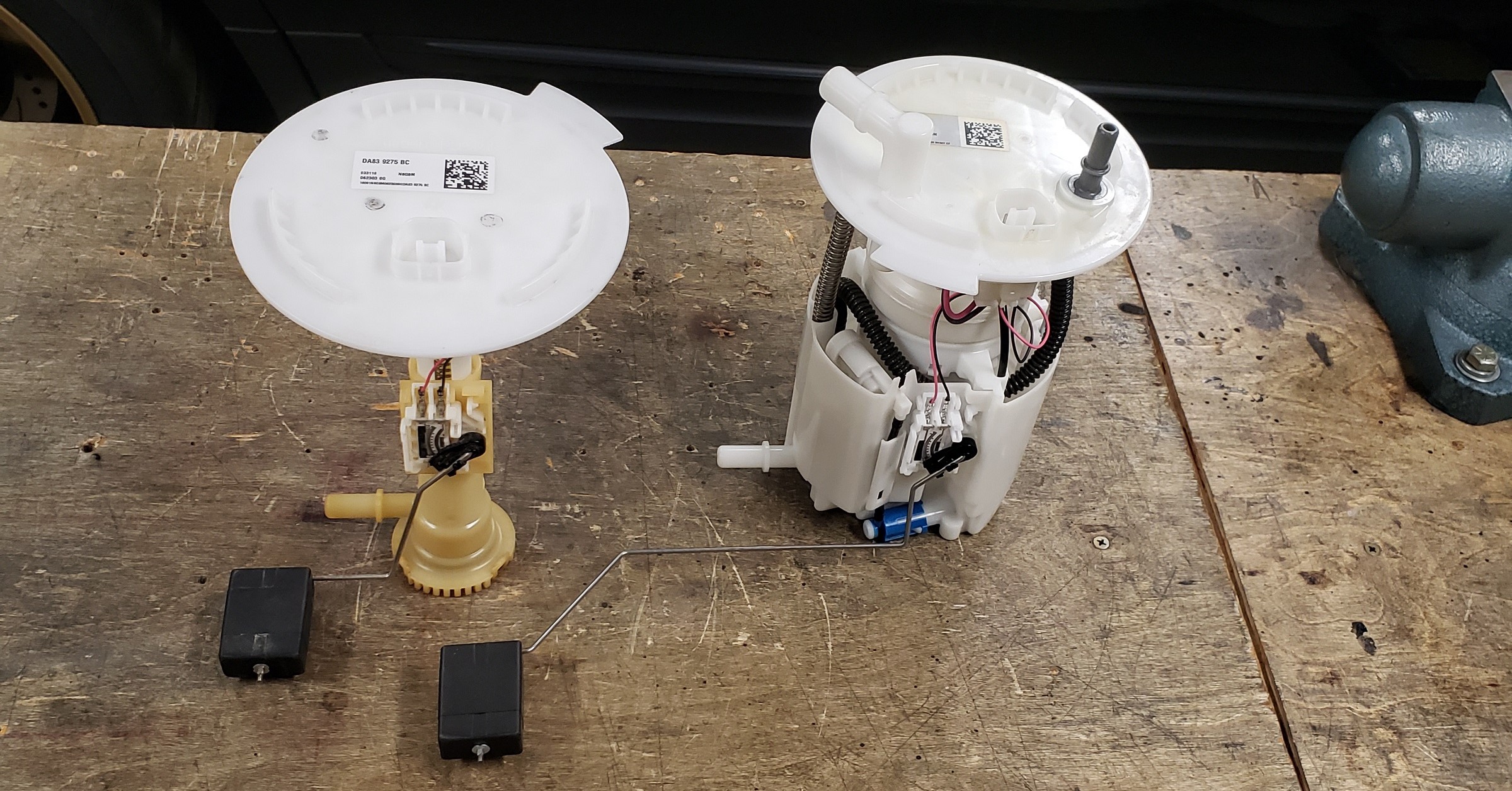
The main fuel pump module, Low Pressure Fuel Pump (LPFP), is located on the passenger side of the saddle tank. On the driver side is not a fuel pump, but essentially a siphon module. There is no pump on this module. It is simple a mechanism to siphon fuel from the bottom of the saddle and send it to the other side.
On the LPFP is what is called a siphon pump (sometimes called a jet pump). It is a pump that uses the Venturi effect of the electric fuel pump to “siphon” fuel from the other side of the tank.
As the fuel pump within the module is flowing fuel, it begins to siphon fuel via the siphon pump from the other fuel siphon module.
But why two fuel-level sending switches (the floats)? The level sending switches are there to indicate the fuel level within each saddle. If the level is equal and operating normal, the floats will be at identical levels. If there is a failure in the siphon pump or some other issue with the siphon module, the level of fuel on either side will be different. With different fuel levels causing different heights on the floats, an error code (likely a P0461 code) will manifest.
Some comparison images of the siphon module and the LPFP.
Following are some close up images of the fuel siphon module itself.
For more information, feel free to read this article posted at www.underhoodservice.com.