NOTICE: As this is an ignition-cut based system and it does not cut fuel. Using this on a vehicle that retains catalysts may cause issues, potentially damaging the catalysts, as they may see unburnt fuel. Per N2MB, keeping the duration of the 2-step short and allowing for proper cool down time can mitigate potential damage to catalysts.
NOTICE: Tuning may be required in order to adjust for the unburnt fuel that is being seen by the O2 sensors during 2-step engagement. Placing the O2 sensors in an Open Loop state for the duration of the 2-step engagement is advised.
Introduction
One way to produce more consistent launches is with a transmission brake or 2-step. There’s been talk of it from time to time on various pages/groups/forums. Well, this idea I can’t take credit for as a friend of mine, Forrest Folmsbee, who also as a pretty bad ass, fast Explorer Sport, turned me onto the value of having a 2-step and shortly after (by coincidence, lol), Jordan Christensen of SHO Forum and YouTube fame, actually brought up the N2MB 2-step controller WOT Box to me and Andrew Bullock (current SHO record holder) as a possible option. Now, the WOT Box is nothing new and has been around for some time. I just hadn’t heard about anyone using it on our application. After speaking with the folks over at N2MB, they said it would work and they produced a wiring schematic for me on the connection process. Though the WOT Box has applications for a wide variety of platforms (contact N2MB for your specific one if unsure), this write-up will cover the 3.5L transverse (the F-150 longitudinal variant has different wiring) twin-turbo EcoBoost. I am unsure how the PCM wiring looks like for the early-generation transverse 3.5L EcoBoost engines (2010-2012 Ford Taurus SHO, 2010-2012 Ford Flex, 2010-2012 Lincoln MKS), so if anyone can verify, feel free to let me know and I’ll update this write-up.
Parts List
Here’s a list of parts that I used. Using all of these can drive up the cost, but I felt it was a way to do it “right”. You can pick and choose what to use or find substitutes as needed. Keep in mind…connections are VERY important. I always prefer Deutsch connectors as they are easy to work with, have positive engagement and are somewhat weatherproof. Crimping is usually preferred over solder (this is done in the automotive, aerospace and military industries for a reason), so that means tooling might have to be an investment if you don’t already have the proper crimping tools, so keep that in mind. I realize that N2MB says to solder…but it isn’t actually a preferred method in many industrial and commercial applications, and that is the standard I typically try to emulate…
- N2MB
- WOT Box, Qty: 1
- McMaster-Carr
- Stranded Wire, Red, 25ft, 16ga, Qty: 1
- Stranded Wire, Orange, 25ft, 16ga, Qty: 1
- Stranded Wire, Purple, 25ft, 16ga, Qty: 1
- 4:1 Heat Shrink Tubing, 0.16″, Qty: 1
- Fuel-Resistant Heat-Shrink Tubing, 0.38″ ID, Qty: 2
- Fuel-Resistant Heat-Shrink Tubing, 0.19″ ID, Qty: 1
- Electrical-Insulating Tube Sleeving, Expandable, 0.170″ ID, 10ft, Qty: 1
- Electrical-Insulating Tube Sleeving, Expandable, 0.120″ ID, 10ft, Qty: 1
- High-Strength Slit Corrugated Sleeving, 3/8″ ID, Black, 25ft, Qty: 1
- Deutsch Connector Store
- Amazon
Fitment
Fitment is essentially late-generation (2013-up) 3.5L transverse twin-turbo EcoBoost that has a PCM that looks like this. It essentially has to have the two main connectors being identified, in your own wiring diagram, as C1551B and C1551E. However, ENSURE the diagrams I am providing (wire #’s and colors) MATCH your wiring diagram. If they are different, feel free to reach out to N2MB for help. Their customer service is great and, although you are messaging via text, they respond quickly and at other normal business hours, too. I am unsure how the PCM wiring for the early-generation (2010-2012) 3.5L differs, but it is still possible, just identifying the different wiring may be required.
The list generally includes (there may be others) these models:
- 2013-2019 Ford Explorer Sport
- 2016-2019 Ford Explorer Platinum
- 2013-2019 Ford Taurus SHO
- 2013-2019 Ford Flex
- 2013-2016 Lincoln MKS
The parts that come with the kit are pretty good and include:
- WOT Box
- WOT Box wiring harness
- Serial-to-USB adapter
- Zip ties, butt connectors
This is essentially a universal kit, so the wording used may confuse a bit, but understand the below:
- Clutch = Brake
- TPS (Throttle Position Sensor) = APP (Accelerator Position Sensor)
Here are the 6 wires that the WOT box needs connected:
WOT Box Pigtail Modification
Not Required
The more I think about this part of the modification, the more I realize I really didn’t need to do it. The harness already separates from the WOT box itself right at the unit. The factory unit uses a Molex-style connector on the body. I’m not really a big fan of Molex, but it’s cheap and will “work”. I always prefer Deutsch connectors and I have a tackle box full of their parts to make harnesses.
So take this part of the mod with a grain of salt and feel free to skip over it, as the main harness can just be integrated into this pigtail. But if you do decide to proceed with it, here are the parts being used:
- DTM04-6P, Qty: 1
- DTM04-6S, Qty: 1
- WM-6P, Qty: 1
- WM-6S, Qty: 1
- 16-18ga Male Pin, Qty: 6
- 16-18ga Female Pin, Qty: 6
- Fray-Resistant Expandable Sleeving, 1/4″ ID, Black, 10ft, Qty: 1
- Fuel-Resistant Heat-Shrink Tubing, Qty: 1
As mentioned, I always prefer crimping and using automotive grade connectors when doing wiring. Deustch products are very easy to get to get your hands on, cost-effective, have a wide variety of applications and are of high quality. You will need a special crimp tool, however, and that can get pricey. If you use the connectors often, it’s an investment worth making.
My crimper. The DMC1186…it’s very versatile and can be used for a number of different manufacturers connectors using different “barrels”. I mainly use Deutsch so this barrel stays attached 99% of the time. And no, I didn’t pay $2500 for this tool, lol. I found an online auction site (wish I could remember it, it was so many years ago) that was auctioning off tooling from businesses closing. I think I picked it up for about $200. Still expensive, but since I build a lot of wire harnesses, it was a good investment…
Main Harness
The next few sections will cover the main harness and the modifications I made for it. Because there are two areas of the engine bay the harness will be going to, I will be bundling and sleeving the wires into 2 separate “legs”.
- Stranded Wire, Red, 25ft, 16ga, Qty: 1
- Stranded Wire, Orange, 25ft, 16ga, Qty: 1
- Fray-Resistant Expandable Sleeving, 1/8″ ID, Black, 10ft, Qty: 2
- Fuel-Resistant Heat-Shrink Tubing, 0.19″ ID, Qty: 1
- Fuel-Resistant Heat-Shrink Tubing, 0.38″ ID, Qty: 1
Make sure to leave the BLACK ground wire outside of the 2 smaller “leg” sleeve runs.
Wiring
Wiring for the main harness is pretty straight forward. Below are part of the drawing set I got from N2MB. Not bad, as they use ProDemand to extract the wiring harness information for their vehicles. They also have you tap/cut into the wires at end where the sensors are located. This can have you going to a number of different places in the are and might require you to do more work than I think its necessary. I have a slightly different philosophy…
…I prefer to place all the wires as close to each other as possible, allowing for minimal runs and minimal locations to access. In this case…instead of tapping/cutting wires at the sensor end…I’m going straight to the PCM side. That way you can keep all the wires together for the majority of their runs. Below are the wiring diagrams I used, in conjunction with theirs, to achieve this. I only had to go to 2 locations, The PCM and the BJB. These schematics are from the factory Ford service manual. I actually like these better…
Red & Orange Wires
The first two WOT Box wires we will deal with are the RED and ORANGE wires, they are the interrupt wiring for the coil-on-plug power supply. The placement of these wires is critical. The RED wire is cut into the side closest to the fuse, while the ORANGE wire is the side closest to the coils. The VIOLET coil-on-plug wire is a common power wire to all 6 ignition coils. You can interrupt it anywhere in the harness, but it’s easier to find, believe it or not, beneath the Battery Junction Box (BJB).
In order to get access to the underside of the BJB, we’ll need to remove the battery source wire, which is a 4ga BLUE WITH RED STRIPE wire. The terminal at the BJB is bent 90 degrees and secured to a screw post. There is not enough slack in this wire to remove it simply lifting. You will need to remove the battery from the battery tray, cut-away some electrical tape wrapping the wire bundle together, then removing that BLUE WITH RED STRIPE wire from the BJB.
Now let’s begin making a connector for the COP wire that you will be intercepting with the WOT box wire. I wanted to make this easily converted to run back to stock if needed, so the connector had to be outside of the BJB wire box.
- 16-18ga Male Pin, Qty: 1
- 16-18ga Female Pin, Qty: 1
- 4:1 Heat Shrink Tubing, 0.16″, Qty: 1
- Stranded Wire, Purple, 25ft, 16ga, Qty: 1
- No-Gap Fine-Adjustment Nylon Cable Tie, Qty: 1
For this part, we will be using Deutsch pins, but without the connector body itself. This could be a place you could solder, but again…there are too many ways soldering can go bad, especially in tight quarters like this place is. Soldering like a professional isn’t quite as easy as it looks (not hard, I get it, but there is a technique to be mindful of). If not done properly, a cold solder joint will break over time and cause all sorts of issues. Better to crimp…
Once the fuse-side wire is extended long enough and you have pulled the other side out side the box, you can close up the BJB as we are done with it. Now onto making the connector for the COP wire assembly.
- Electrical-Insulating Tube Sleeving, Expandable, 0.170″ ID, 10ft, Qty: 1
- DTM04-2P, Qty: 1
- DTM06-2S, Qty: 1
- WM-2P, Qty: 1
- WM-2S, Qty: 1
- 16-18ga Male Pin, Qty: 2
- 16-18ga Female Pin, Qty: 2
As I wanted this to be able to go back to stock if needed, I had to create a jumper wire “dongle” to achieve that. This part is just kept stored in the car somewhere should I need it in order to remove the WOT box, but it isn’t need to run the 2-step.
Yellow, Green & Blue Wires
Next set of wires are the remaining 18ga YELLOW, GREEN and BLUE wires. These will be run right to the PCM, making it a bit easier to keep the wires bundled together instead of running them each to separate locations in the car. In order to make things a bit easier to access, you’ll need to get access to the PCM (check out this write-up here), remove the two main PCM connectors, then remove some of the tape bundling the wires together as they enter the connector. They are both C1551, but one is “E” and the other is “B”. I marked them with a paint pen to make it easier to identify.
- Wiring Tee Connector, Single Pin for 16-20ga, Qty: 3
- High-Strength Slit Corrugated Sleeving, 3/8″ ID, Black, 25ft, Qty: 1
- Tesa High Heat Harness Tape 51036, Qty: 1
- Electrical-Insulating Tube Sleeving, Expandable, 0.120″ ID, 10ft, Qty: 1
- DTM06-3S, Qty: 1
- WM-3S, Qty: 1
- 16-18ga Female Pin, Qty: 3
The YELLOW wire is the signal going to Ignition Coil #1, we WILL NOT be cutting this, just tapping into it and it is on the “E” connector (the connector facing the rear of the vehicle).
In order to ensure I had the proper wire pulled, I used my multimeter to run a continuity check on PIN 42 (with the connector removed and test lead stuck into PIN 42 location) and a wire back probe (a very sharp needle that essentially penetrates the insulation). Once I verified I had the correct one identified, I used the Tee Taps to install the YELLOW wire.
The GREEN wire is for the Brake Pedal Position (BPP) sensor. This wire WILL NOT be cut, but tapped into, just as with the yellow wire. This wire is located on the “B” PCM connector (facing the front of the vehicle) of the PCM, PIN 66.
It is identified in the same way the YELLOW wire was verified, using the multimeter with a back probe. Once identified, it is also tapped using one of the Tee Taps.
Finally, the BLUE wire. This wire is for the Accelerator Pedal Position (APP) sensor. What makes this one unique is that it has 2 outputs for redundancy. In this application we will tap into the second APP2 wire. Following the same procedure as the YELLOW and GREEN wires. It’s located on the “B” PCM connector, PIN 54. This one gave me the most trouble as there are, I think, 4 wires in the bundle that are BLUE WITH WHITE STRIPE. And it was buried in the middle of the bundle too…was tough to get it teased out enough to get the Tee Tap onto it.
Now onto getting the main wire harness from the cabin into the engine bay. I did this part mostly on video. Check out the YouTube video below for this final portion of the installation. You’ll need a few rubber grommets for this part.
In the cabin, with the passenger side “A” pillar cover removed.
In the engine bay, on the passenger side with the wiper cowl removed.
Final part I need to do is make the main power wire going from the battery to the BJB a bit more presentable. For now, this works. Once I do that, I will update this post.
Initial Setup
When you’ve completed wiring of the WOT Box and after downloading and installing the WOT Box software (which can be downloaded here), you will connect the WOT Box to your laptop with the provided serial-to-USB adapter. Ensure you are KEY ON, ENGINE OFF.
This is the standard screen first opening the software before connecting to the WOT Box.
The instructions say connect using COMM Port set to AUTO, but that didn’t work for me. I needed to select COMM Port 8, but this will differ for each individual laptop. Just go test each one from the drop down menu and select READ to see if it connects.
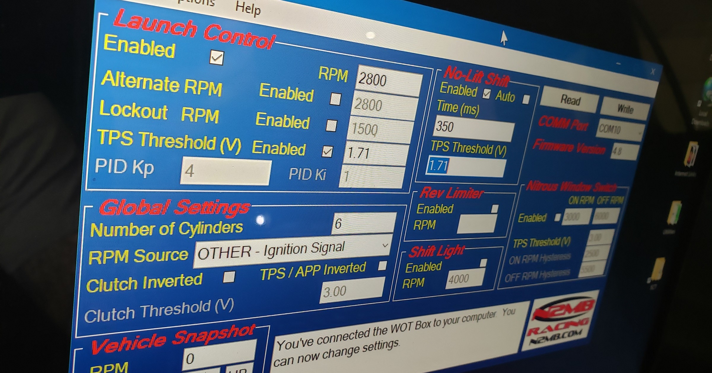
Once the correct port is identified and selecting READ, you see that you’re connected by the notes in the bottom center text box. This is simply a screen shot of what is stored in the WOT Box when you press read. It is not a live, real-time updated screen. You’ll have to press READ each time you want to see an updated snapshot of the WOT Box settings. I used the settings indicated in the picture below. With the turbos I have and the boost that I am desiring at launch, I am set to 2800RPMs. This has given me a pretty consistent 10PSI of boost. I tried 2500RPM before that and it built only 4PSI of boost. Your application may require different settings based on how your tune is setup, and what mods you have.
My settings:
- Launch Control Enabled: YES
- Launch Control RPM: 2800
- TPS Threshold Enabled: YES
- TPS Threshold Voltage: 1.71
- Number of Cylinders: 6
- RPM Source: OTHER – Ignition Signal
- No-Lift Shift Enabled: YES
- Time (ms): 350
- TPS Threshold: 1.71
The TPS Threshold is actually the APP range. Because it is connected to APP2, the range is 0.00v to 2.00v. WOT is 2.00v, but you want the threshold set to a little before that, hence the 1.71v. You can experiment with how far down the pedal goes and what the voltage is by pressing the accelerator pedal, then selecting READ. At the bottom left of the screen is a VEHICLE SNAPSHOT. If the pedal is past the voltage point set in your settings, then it will show as DN (pedal depressed), if not it will show as UP (no foot on pedal). This holds true for CLUTCH (which in our case is actually the BPP). BPP range is 0.00v to 5.00v
Testing
If you want a hardcopy to print out and have handy, download HERE.
Conduct these 5 tests to ensure the functionality of the 2-step:
- KEY ON, ENGINE OFF. Press the ACCELERATOR pedal to the floor. You should see the LED on the WOT Box start to blink. If it doesn’t, check your Accelerator Pedal Position sensor signal connection (WOT Box BLUE wire).
- Next, with the ACCELERATOR pedal still depressed, press the BRAKE pedal to the floor. You should see the LED on the WOT Box briefly go out, and then come back on solid for one second and then finally resume blinking. If you do not see this, check your Brake Pedal Position sensor signal connection (WOT Box GREEN wire).
- Next, unplug the WOT Box from the WOT Box wiring harness. Make sure the car will not run with the WOT Box unplugged. It should crank but not start. If it does start, or starts and runs on a few cylinders, then the RED / ORANGE wire connections are incorrect. Make sure the POWER for all the ignition coils has been cut and is now running THROUGH the WOT Box. The WOT Box RED wire should be connected to the +12V source for all the coils, the WOT Box ORANGE wire should be connected to the same wire, but on the side that provides +12V power to the coils (RED TOWARDS fuse and ORANGE TOWARDS coils).
- Reconnect the WOT Box and start the engine. Place the transmission in NEUTRAL. Press the ACCELERATOR pedal to the floor and immediately press the BRAKE pedal to the floor. You should hear the engine begin to rev up, stumble for a short period while the ignition is cut, then return back on and continue revving. Remove your foot from the ACCELERATOR before you hit the rev limiter. The 2-step WILL NOT engage if the ACCELERATOR is depressed before the brake. This is normal. If the engine does not stumble or pause when the LED turns out, then check the RED and ORANGE wires. Verify that the WOT Box RED wire and WOT Box ORANGE wire are connected the proper way. If they are reversed, the ignition cut will not work.
- Lastly, test the 2-step. Before engaging the 2-step, make sure the engine is idling below 1500RPM in NEUTRAL. Press the BRAKE pedal down and then press the ACCELERATOR pedal all the way down. The ACCELERATOR pedal must be floored for the 2-step to engage. The engine should rev up to the desired RPM and hold. If it does not, be sure to remove your foot from the gas before you hit the rev limiter. If the 2-step does not work, check the WOT Box YELLOW wire.
Now go out and make some test runs. Remember, the 2-step WON’T engage unless the brake is pressed first AND the gas is pressed second down to WOT.